[0033] Hereinafter, preferred embodiments of the real-time PCR system according to the present invention are described with reference to the accompanying drawings. It should be noted that the drawings show preferred embodiments of the invention by way of example, and the invention should not be construed narrowly by the preferred embodiments.
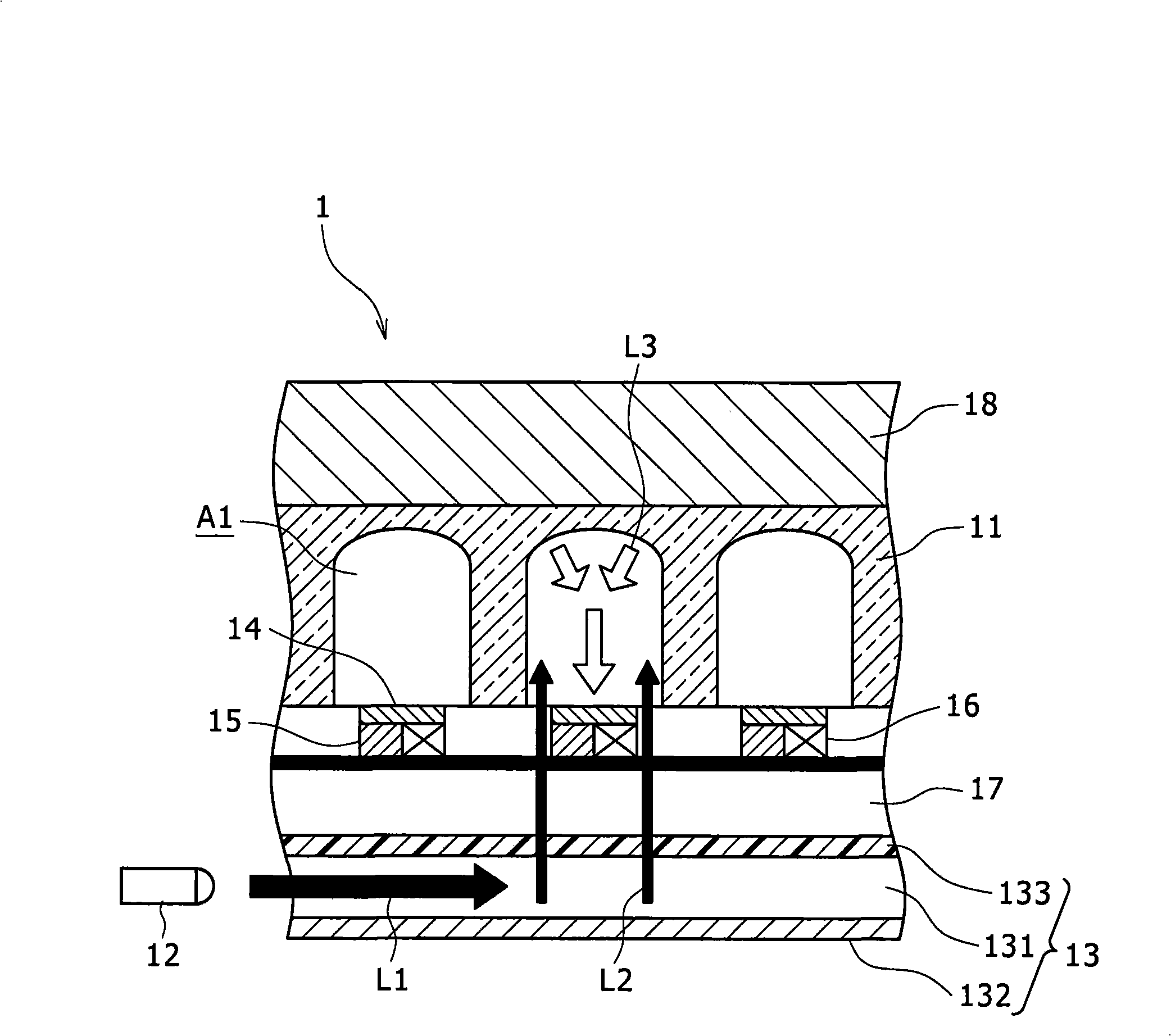
[0034] First, refer to figure 1 , the first embodiment of the real-time PCR system according to the present invention will be described hereinafter.
[0035] figure 1 Reference number 1 in indicates the first embodiment of the real-time PCR according to the present invention. As desired, the size and layer structure of the real-time PCR system 1 can be selectively determined according to the purpose of application. As long as the real-time PCR system 1 can achieve the purpose of the present invention, the configuration of the real-time PCR system 1 can also be designed or improved as required.
[0036] The real-time PCR system 1 is provided with a well substrate 11 in which a plurality of reaction areas A1 are defined, a light source 12 , and an excitation light scanning plate 13 for guiding excitation lights L1 , L2 emitted from the light source 12 . In addition, a filter 14 , a fluorescence detector 15 for detecting fluorescence L3 , and a heater 16 for heating the reaction region A1 are respectively arranged on the measurement substrate 17 .
[0037] In the real-time PCR system 1, the excitation light L1 emitted from the light source 12 is guided through the excitation light scanning plate 13, and then irradiated as the excitation light L2 into each reaction region A1. Next, the light L3 emitted from the reaction area A1 is detected and measured by the corresponding fluorescence detector 15 .
[0038] The real-time PCR system 1 of the first embodiment is characterized in that each reaction area A1 is provided with a corresponding heating part 16, and the heating part 16 is provided with a temperature detector and a controller, and the temperature detector is used to detect the heat source of the heating part 16 nearby temperature and convert this temperature into an electrical signal, the controller is used to control the thermal dose from the heat source based on the correlation between the pre-stored electrical signal and the heat value of the heat source. Therefore, the real-time PCR system 1 can control the temperature of each reaction area A1 individually and with high precision. It should be noted that the calorific value of each heat source can be estimated by measuring, for example, the exothermic temperature of each heat source. Each element of the real-time PCR system will be described in detail below.
[0039] The well substrate 11 is provided with a plurality of reaction regions (wells) A1. Predetermined reactions are to be carried out in these areas A1 respectively. For example, the well substrate 11 may be formed of a low fluorescent plastic material or glass material, and as many reaction regions A1 as the number of human genomes may be arranged in a matrix.
[0040] In the present invention, the reaction area (well) for the PCR reaction may desirably be in the form of a microcavity. For example, when each well is formed to a size of 300 μm×300 μm×300 μm (capacity: about 30 nL) and about 40,000 such wells are arranged, the resulting device has a thickness of about 6 cm 2 area.
[0041] The shape of each reaction area A1 is not particularly limited, and each reaction area A1 may be of any shape within the range that it can retain the reaction mixture. A desired appropriate shape can be selected while considering the optical path through which the excitation lights L1 , L2 are introduced and irradiated, the optical path used for detecting the fluorescence L3 and the like. Since the real-time PCR system 1 needs to reflect the fluorescence L3 in each reaction area A1, each reaction area A1 is provided with a curved area.
[0042] In order to suppress a decrease in detection sensitivity due to light scattering and the influence of external light, desirably, the reaction region A1 may be coated with a light-shielding material (for example, diamond-like carbon, etc.).
[0043] This first embodiment uses a light source 12 and an excitation light scanning plate 13 as an optical device capable of irradiating excitation light of a specific wavelength to all reaction regions A1, and the excitation light scanning plate 13 guides excitation light L1 to a plurality of reaction regions in each of A1.
[0044] The type of light source 12 is not particularly limited as long as it can emit light of a specific wavelength. Preferably, white or monochrome light emitting diodes (LEDs) may be used. The use of such light emitting diodes makes it possible to easily obtain light that does not include unnecessary ultraviolet rays or infrared rays.
[0045] No particular limitation is imposed on the installation position of the light source 12 or the number of such light sources. Although not shown in the drawing, a structure may be employed in which a plurality of light sources are arranged corresponding to each reaction area A1 so that excitation light from each light source can be directly irradiated to its corresponding reaction area A1. This structure can directly irradiate each reaction region through the corresponding light source of each reaction region, so that a larger amount of excitation light can be irradiated, and in addition, the amount of excitation light L1, L2 can be individually controlled. Therefore, the excitation lights L1, L2 can be irradiated to the respective reaction regions A1 at equal levels.
[0046] The excitation light scanning plate 13 is used to guide the laser light L1 that has been emitted from the light source 12 to each reaction area A1 in the well substrate 11 . The excitation light L1 emitted from the light source 12 is introduced into a spacer 131 formed in the excitation light scanning plate 13 . The reflective film 132 is arranged in a lower portion of the excitation light scanning plate 13 so that the excitation light L2 can be guided to the well substrate 11 . Therefore, the fluorescent material on the probes in the reaction mixture in each reaction area A1 can be excited by an equal amount of excitation light. The material of the reflective film 132 is not particularly limited. However, dichroic mirrors may be used desirably.
[0047] In this first embodiment, an optical filter 133 that transmits only light of the wavelength of the excitation light L1 , L2 may desirably be arranged in the upper portion of the laser scanning panel 13 . The filter 133 can efficiently extract the excitation light L2 from the light emitted from the light source 12 and introduce the excitation light into each reaction region, for example, a polarizing filter or the like can be used as the filter 133 .