Quasi-stable state method solid body thermal conductivity measurement instrument

A technology of thermal conductivity and measuring instruments, which is applied in the experimental measurement of solid thermal conductivity and the field of solid thermal physical property testing, and can solve the problems of uneven heating of the heating plate, time-consuming and laborious, and narrow measurement range of solid thermal conductivity.

Inactive Publication Date: 2008-11-12
XI AN JIAOTONG UNIV
View PDF0 Cites 48 Cited by
  • Summary
  • Abstract
  • Description
  • Claims
  • Application Information

AI Technical Summary

Problems solved by technology

[0004] The quasi-steady-state method has the advantages of lower requirements on the selection of heat sources, shorter measurement time and lower requirements on the insulation of the sample, but it is difficult to ensure that the boundary conditions in the experiment are the same as those given in the theoretical analysis. Consistent, and it is difficult to accurately obtain the required temperature change law
The temperature difference of existing quasi-steady-state measuring instruments is mostly calculated by thermocouples measuring the temperatures of cold and hot surfaces respectively; the potential difference of thermocouples is usually read by manual use of potentiometers, which has poor accuracy and cannot be realized. Automation; the heating plate has the problem of uneven heating, so there is a big gap with the theory; at the same time, every time the thermal conductivity is measured, it is necessary to first carve a groove on the sample and embed the thermocouple, so that when the sample is prepared Time-consuming and labor-intensive; and the measurement range of solid thermal conductivity is narrow, generally not exceeding 2W / (m·K)

Method used


Image

  • Quasi-stable state method solid body thermal conductivity measurement instrument
  • Quasi-stable state method solid body thermal conductivity measurement instrument
  • Quasi-stable state method solid body thermal conductivity measurement instrument

Examples


Embodiment Construction

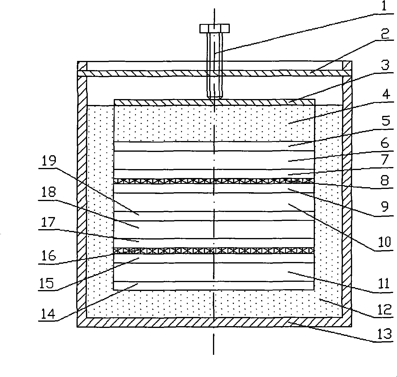
[0022] refer to figure 1 , quasi-steady-state thermal conductivity measuring instrument, comprising: a measuring container 13, the upper end of the measuring container 13 is provided with a stainless steel cover 2, the middle of the cover 2 is threaded, and a bolt 1 is installed. The measuring container 13 is filled with thermal insulation material 12, and the center of the thermal insulation material 12 forms a cavity, the upper part of the cavity is provided with a thermal insulation cover 4, and the upper part of the thermal insulation cover 4 is provided with a pressing metal sheet 3, the thickness of which can be 2 to 5 mm. Aluminum sheet or stainless steel sheet. The bolt 1 squeezes and compresses the metal sheet 3, and the extrusion force can be adjusted by adjusting the bolt 1 up and down.

[0023] In the middle of the cavity of the thermal insulation material 12, the first soaking metal sheet 5 with the first thermocouple, the first sample 6, the second soaking metal...


PUM

PropertyMeasurementUnit
thermal conductivityaaaaaaaaaa
thicknessaaaaaaaaaa

Abstract

The invention discloses a quasi-stable state method thermal conductivity measurement apparatus, which includes a direct-current power supply, a data acquisition processing system, two heating plates respectively connected to the direct-current power supply, four thermo-electric couples connected to the data acquisition processing system, four identical samples, seven soaking metal sheets and a measurement container stuffed with thermal insulation material. The thermal conductivity measurement apparatus is characterized in that the upper end of the measurement container is provided with a cover, screw threads are machined in the center of the cover and mounted with a bolt, the bolt presses a compressing metal plate above the heat preserving cover, to decrease the inside contact resistance. Two thin film heating plates with staggered structure are adopted, thereby heating on the samples are uniform. The soaking metal plate is provided with grooves, and the corresponding thermo-electric couples are fixed in the grooves by heat conducting glue, the soaking metal plate further uniforms the heat produced by the heating plate, and grooving on the sample is not needed during test, thereby the experimental investigation to different solid thermal conductivities can be conveniently executed.

Description

technical field [0001] The invention relates to the technical field of solid thermophysical property testing, in particular to the field of experimental measurement of solid thermal conductivity, in particular to a quasi-steady-state solid thermal conductivity measuring instrument. Background technique [0002] As an important physical parameter of matter, thermal conductivity has important uses in the fields of chemical engineering, materials, energy, power and refrigeration engineering, and is an indispensable basic data in many industrial processes and product designs. With the rapid development of modern industry, the measurement of thermal conductivity of solid materials has been paid more and more attention by people. [0003] The thermal conductivity of a substance can be obtained through experimental measurement, theoretical calculation or computer simulation, but at present it is still mainly based on experimental measurement. According to the experimental measurem...

Claims


Application Information

Patent Timeline
Patent Type & Authority Applications(China)
IPC IPC(8): G01N25/20G01N25/18
Inventor 吴江涛李晓静
Owner XI AN JIAOTONG UNIV
Why Eureka
Try Eureka