System and method for mask verification using an individual mask error model

A mask error and model simulation technology, applied in the field of optical lithography, can solve problems such as long time and large quantities

Inactive Publication Date: 2008-11-12
ASML NETHERLANDS BV
View PDF4 Cites 30 Cited by
  • Summary
  • Abstract
  • Description
  • Claims
  • Application Information

AI Technical Summary

Problems solved by technology

As a result, if any systematic mask error has been introduced in the mask manufacturing process, it may take a long time and a large number of printed wafers to unambiguously detect and correct such error

Method used


Image

  • System and method for mask verification using an individual mask error model
  • System and method for mask verification using an individual mask error model
  • System and method for mask verification using an individual mask error model

Examples


Embodiment Construction

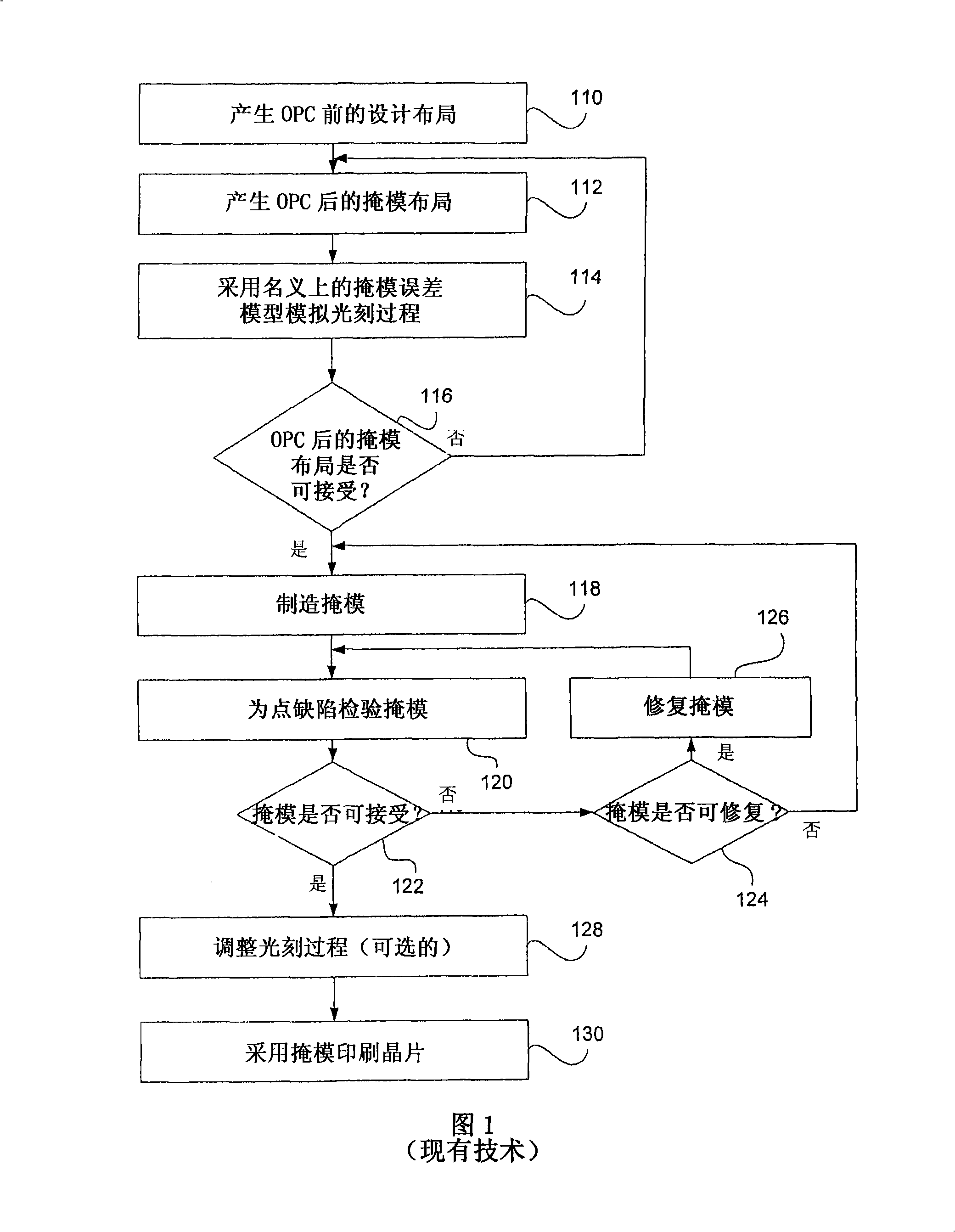
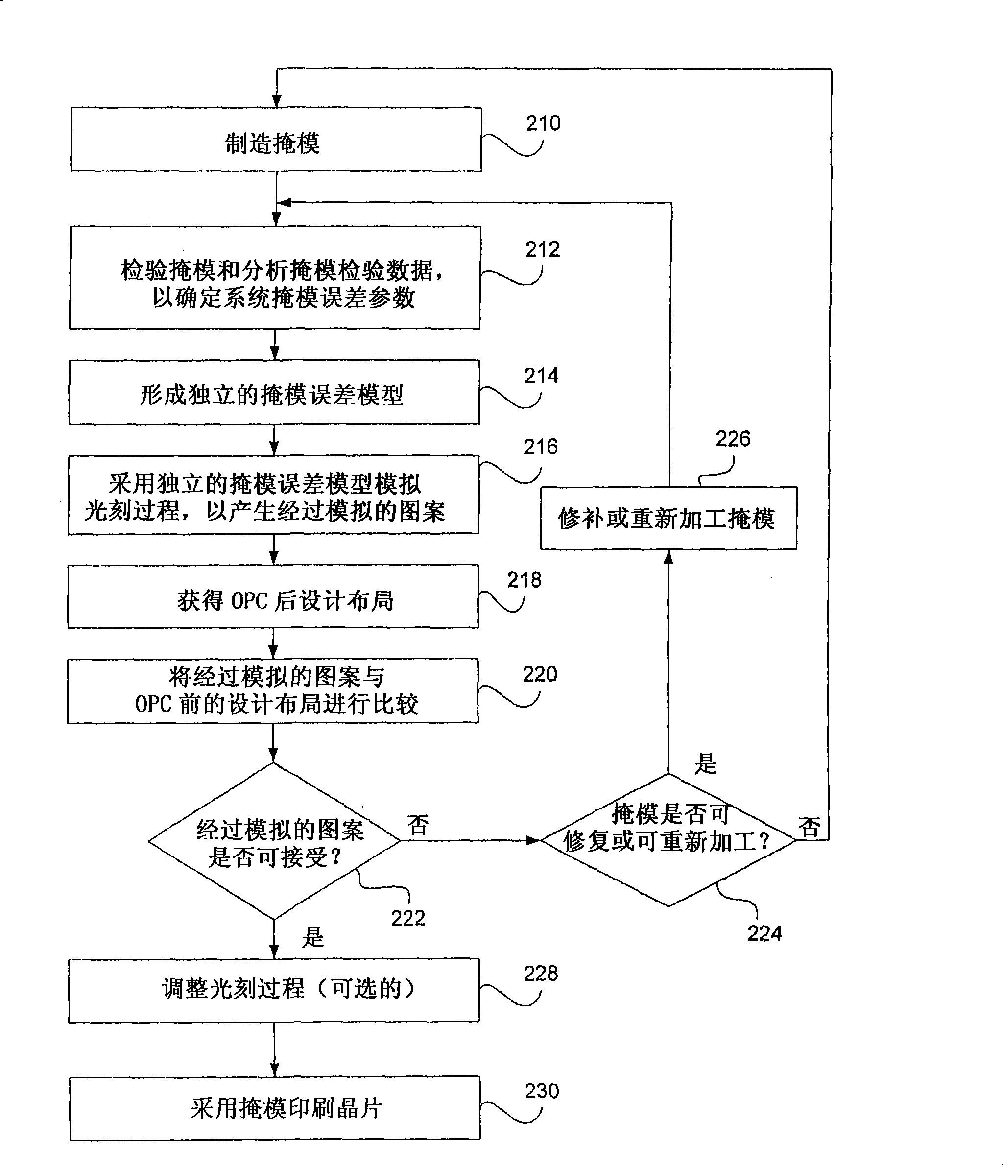
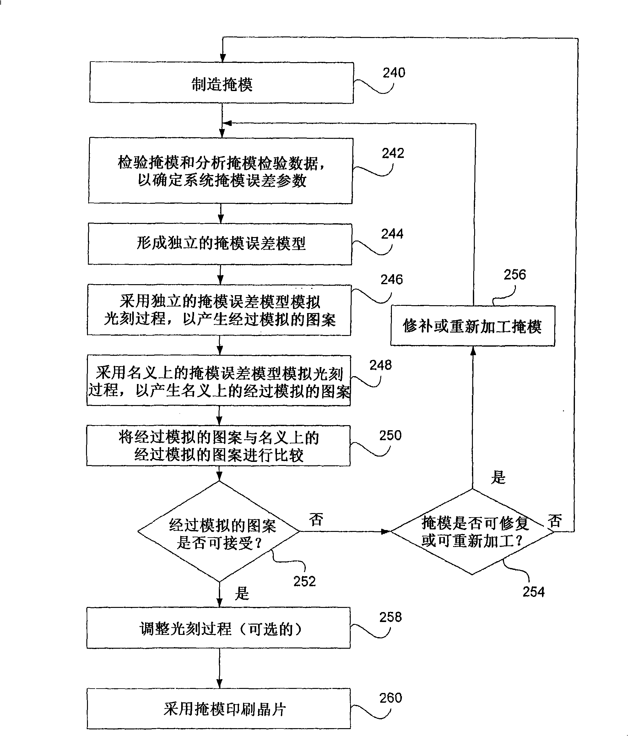
[0038] In practice, due to the defect of the mask manufacturing tool and the change of the mask manufacturing process, the error (or defect, after which the "defect" and "error" can be used interchangeably) is changed from the mask layout after OPC to the actual mask. The pattern transfer process is always introduced into the final manufactured mask. The mask error is the difference between the mask pattern manufactured and the ideal post-OPC mask layout intended to be manufactured on the mask. Generally, mask errors are divided into two categories: random mask errors and systematic mask errors. Random mask errors are errors that cannot be described by models but appear randomly and statistically on the manufactured mask, such as excessive particles and small holes. System mask errors are errors that can be described with a model, where the model depends on the pattern environment (eg, local pattern density, pattern size, pattern spacing, and pattern orientation) and / or pattern po...


PUM


Abstract

Methods and systems are disclosed to inspect a manufactured lithographic mask, to extract physical mask data from mask inspection data, to determine systematic mask error data based on differences between the physical mask data and mask layout data, to generate systematic mask error parameters based on the systematic mask error data, to create an individual mask error model with systematic mask error parameters, to predict patterning performance of the lithographic process using a particular mask and / or a particular projection system, and to predict process corrections that optimize patterning performance and thus the final device yield.

Description

[0001] cross reference [0002] This application claims priority from US Provisional Patent Application No. 60 / 719,837 with the title of "System and Methods for Model-Based Mask Verification", and the subject matter of the related application is incorporated herein by reference in its entirety. Technical field [0003] The present invention mainly relates to optical lithography, and more specifically relates to mask verification using an independent mask error model. Background technique [0004] The integrated circuit industry has maintained a high growth rate from the beginning by driving increased device functions at lower costs. Nowadays, rising edge devices provide the computing functions of the computer that once occupied the entire room at only a fraction of the original cost. Many low-cost consumer devices today include features that could not be achieved at any cost just a few years ago, such as video phones, ultra-portable media players, and wireless or ultra-wideband In...

Claims


Application Information

Patent Timeline
Patent Type & Authority Applications(China)
IPC IPC(8): G03F1/00G03F9/00G03C5/00G06F17/50
CPCG03F1/144G03F7/70441G03F1/36G03F1/84G03F7/705G06F17/5081G06F30/398G03F1/72G21K5/00
Inventor 叶军斯蒂芬·亨斯克
Owner ASML NETHERLANDS BV
Why Eureka
Try Eureka