Liquid crystal display panel, LCD device and electronic equipment

A liquid crystal display panel and liquid crystal layer technology, applied in the fields of electronic equipment and liquid crystal display devices, can solve problems such as damage, large space, occupation, etc., and achieve the effect of reducing the overall cost

Active Publication Date: 2008-11-19
KUSN INFOVISION OPTOELECTRONICS
View PDF0 Cites 79 Cited by
  • Summary
  • Abstract
  • Description
  • Claims
  • Application Information

AI Technical Summary

Problems solved by technology

[0005] However, the problem is that the antenna is often installed outside the electronic equipment, and it is easy to be accidentally damaged during use. For example, the external receiving antenna of the TV is often damaged by lightning, flying birds, etc., which affects normal use; in order to ensure reliable The transmitting and receiving capability of the external antenna is usually designed into a certain shape, which not only takes up a large space but also has a high manufacturing cost. With the development of portable and miniaturized electronic equipment, it is necessary to Improved external antenna

Method used


Image

  • Liquid crystal display panel, LCD device and electronic equipment
  • Liquid crystal display panel, LCD device and electronic equipment
  • Liquid crystal display panel, LCD device and electronic equipment

Examples


Embodiment 1

[0064] This embodiment 1 describes in detail the liquid crystal display panel in which the antenna is arranged on the side of the color filter substrate facing away from the liquid crystal layer with reference to the accompanying drawings.

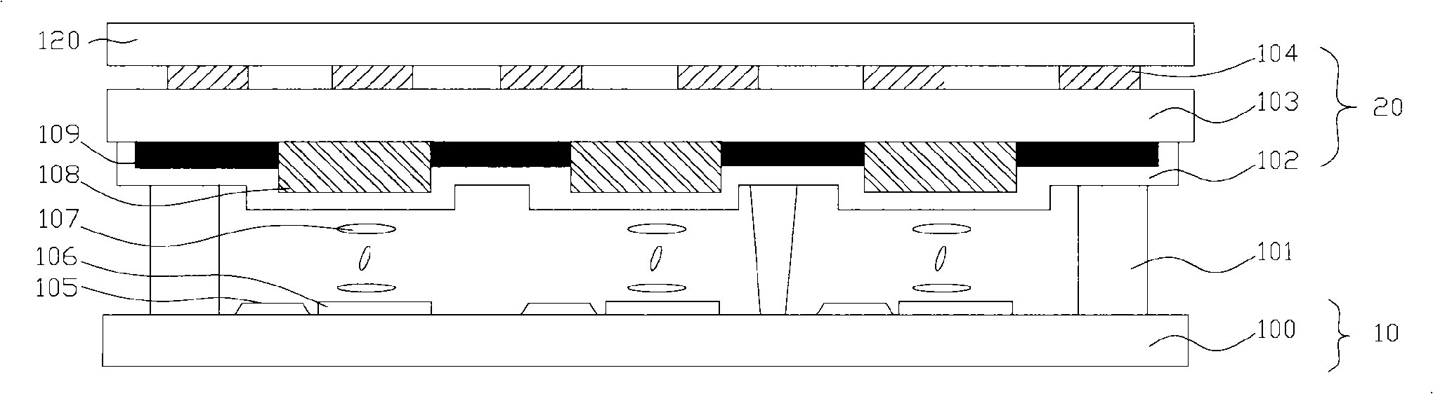
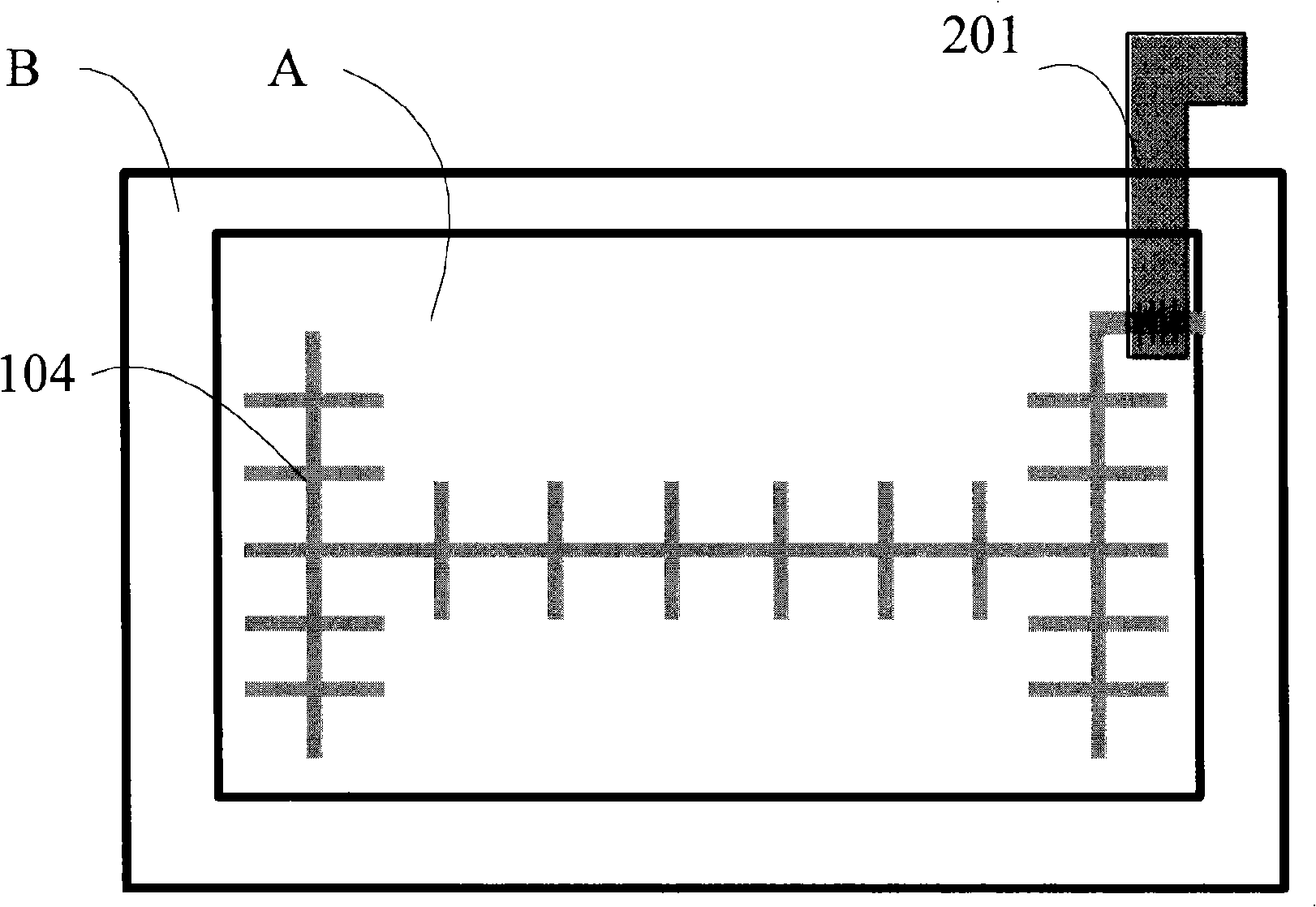
[0065] The following combination figure 2 and image 3 The liquid crystal display panel of one of the first embodiments will be described.

[0066] figure 2 It is a schematic cross-sectional view of a liquid crystal display panel in one of the first embodiments, as figure 2 As shown, the liquid crystal display panel includes: a color filter substrate (also called an upper substrate, the same below) 20 and an array substrate (also called a lower substrate, the same below) 10 arranged oppositely, and the liquid crystal filled between the two substrates Layer 107, the first polarizer 120 on the side of the color filter substrate 20 facing away from the liquid crystal layer 107, the second polarizer (not shown) on the side of the array s...

Embodiment 2

[0077] The second embodiment describes in detail the liquid crystal display panel in which the antenna is arranged in the first polarizer with reference to the accompanying drawings.

[0078] The following combination Figure 5 The liquid crystal display panel of the second embodiment 1 will be described.

[0079] refer to Figure 5 As shown, a polarizer 110 is provided on the side of the first glass substrate 103 in the color filter substrate 20 facing away from the liquid crystal layer 107, and the side of the polarizer 110 facing the first glass substrate 103 includes an antenna 114. The antenna 114 is located in the display area of ​​the liquid crystal display panel, then it should be composed of a pattern of a transparent conductive oxide film, and the transparent conductive oxide film is, for example, indium tin oxide; if the antenna 114 is located in the non-display area of ​​the liquid crystal display panel, it can also be It is composed of a pattern of a metal film ...

Embodiment 3

[0084] Embodiment 3 describes in detail the liquid crystal display panel in which the antenna is integrated on the side of the color filter substrate facing the liquid crystal layer with reference to the accompanying drawings.

[0085] Figure 7 It is a schematic cross-sectional view of the liquid crystal display panel described in the third embodiment.

[0086] Such as Figure 7As shown, the liquid crystal display panel includes: a color filter substrate 21 and an array substrate 11 arranged opposite to each other, a liquid crystal layer 107 filled between the two substrates, and a layer on the side of the color filter substrate 21 facing away from the liquid crystal layer 107 The first polarizer 111 , the second polarizer (not shown) on the side of the array substrate 11 facing away from the liquid crystal layer 107 , and the sealant 101 sealing the liquid crystal layer 107 between the two substrates. The structure of the array substrate 11 is similar to that of Embodiment...


PUM


Abstract

The invention provides a liquid crystal display panel comprising: an upper base plate and a lower base plate relatively arranged, a liquid crystal layer between the upper and lower base plates, and a first polarizer on one face of the upper base plate backing the liquid crystal layer; the upper base plate at least includes a first base plate; the lower base plate at least includes a second base plate and a pixel electrode layer and a thin-film transistor array positioned on the second base plate; and the liquid crystal display panel is provided with an antenna composed of graphics of a conductive film. Correspondingly, the invention also provides a liquid crystal display device and an electronic device. The liquid crystal display panel is provided with the antenna for receiving or transmitting signals, the antenna does not occupy space independently, and will not be broken easily by external factors, in addition, the processes of additional design and making the complementary antenna are also saved, and the whole costs can be reduced.

Description

technical field [0001] The invention relates to the technical field of liquid crystal display, in particular to a liquid crystal display panel, a liquid crystal display device and an electronic device. Background technique [0002] A liquid crystal display (Liquid Crystal Display, LCD) has many advantages such as thinness, energy saving, and no radiation, so it has gradually replaced the traditional cathode ray tube (CRT) display. Currently, liquid crystal displays are widely used in high-definition digital televisions, desktop computers, personal digital assistants (PDAs), notebook computers, mobile phones, digital cameras and other electronic equipment. [0003] A liquid crystal display is generally composed of a liquid crystal display panel and its external drive circuit, while electronic devices such as mobile phones and digital TVs also have separate antennas outside the liquid crystal display for receiving or transmitting data signals, such as transmitting received ext...

Claims


Application Information

Patent Timeline
Patent Type & Authority Applications(China)
IPC IPC(8): G02F1/13G02F1/1333G02F1/1335G02F1/1362G09G3/36
Inventor 简廷宪乔艳冰向贤明李奇典
Owner KUSN INFOVISION OPTOELECTRONICS
Why Eureka
Try Eureka