Semiconductor device of sensing type and its manufacture

A semiconductor and manufacturing technology, applied in the field of sensing semiconductor devices, can solve problems such as increased manufacturing process cost

Inactive Publication Date: 2008-11-19
SILICONWARE PRECISION IND CO LTD
View PDF1 Cites 14 Cited by
  • Summary
  • Abstract
  • Description
  • Claims
  • Application Information

AI Technical Summary

Problems solved by technology

[0012] Another object of the present invention is to provide a sensing type semiconductor device and its manufacturing method, so as to avoid the problem of increasing the cost of the manufacturing process caused by direct sputtering to form the circuit

Method used


Image

  • Semiconductor device of sensing type and its manufacture
  • Semiconductor device of sensing type and its manufacture
  • Semiconductor device of sensing type and its manufacture

Examples


no. 1 example

[0051] see Figure 2A to Figure 2K , is a schematic diagram of a first embodiment of the sensing semiconductor device and its manufacturing method of the present invention.

[0052] Such as Figure 2A and Figure 2B As shown, a transparent carrier 20 such as glass is provided, so as to form titanium tungsten / copper (TiW / Cu) or titanium / vanadium nickel on the transparent carrier 20 by sputtering (sputtering). (Ti / NiV) or the like thin conductive layer 21; then cover the resistance layer 22 on the thin conductive layer 21, and make the resistance layer 22 formed with an opening 220 to expose the part of the thin conductive layer 21; A metal line 23 is formed on the thin conductive layer 21 in the resistance layer opening 220, and the metal line 23 can be copper (Cu) / nickel (Ni) or copper (Cu) / tin (Sn) or copper (Cu) / nickel ( Ni) / Solder (Solder), the thickness is about 3-10μm.

[0053] Then the resistance layer 22 and the thin conductive layer 21 covered by the resistance lay...

no. 2 example

[0068] see Figure 3A to Figure 3D , is a schematic diagram of a second embodiment of the sensing semiconductor device and its manufacturing method of the present invention. In addition, to simplify description and drawings, the same or similar components corresponding to the above-mentioned embodiments are denoted by the same numbers.

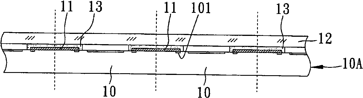
[0069] This embodiment is substantially the same as the previous embodiment, the main difference is that a dielectric layer covering the sensing chip and metal lines and filling between the sensing chips is directly formed on the transparent carrier board, and the second dielectric layer is omitted. Manufacturing process.

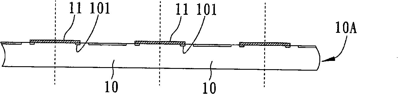
[0070] Such as Figure 3A As shown, a light-transmitting carrier 20 with a plurality of metal lines 23 formed on the surface is provided, so that a thinned and good sensing chip 25 is connected to and electrically connected to the light-transmitting carrier 20 through its conductive bumps 255. on the metal line 23.

[007...

no. 3 example

[0077] see Figure 4 , is a schematic diagram of a third embodiment of the sensing semiconductor device and its manufacturing method of the present invention. In addition, to simplify description and drawings, the same or similar components corresponding to the above-mentioned embodiments are denoted by the same numbers.

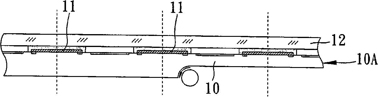
[0078] The sensing semiconductor device and its manufacturing method of this embodiment are substantially the same as those of the previous embodiments, the main difference is that a dam structure (dam) 201 is pre-set around the sensing area of ​​the corresponding sensing chip on the light-transmitting carrier 20, For the sensing chip 25 to be connected to the metal circuit 23 through the conductive bump 255, and when the first dielectric layer 24 is filled between adjacent sensing chips 25, the first dielectric layer can be effectively controlled to avoid the 24 covers the sensing area 253 of the sensing chip 25 .


PUM


Abstract

A sensing semiconductor device and the fabrication method thereof are disclosed. A plurality of metal lines are developed on a light-transmitting carrier plate; a plurality of sensing chips which are processed with thickness reduction and chip probing in advance and are provided with conductive lug bosses on the solder pads are electrically connected to the metal lines on the light-transmitting carrier plate; a first dielectric layer is filled among the sensing chips to cover the metal lines and the areas around the sensing chips; a second dielectric layer and a groove exposed outside the metal lines are developed on the sensing chips and on the first dielectric layer; a plurality of leads electrically connected to the metal wires are arranged on the second dielectric layer; incision is carried out among the sensing chips so as to form a plurality of sensing semiconductor devices. In this way, problems of line rapture due to that the included angle at the joint of the lines is acute, poor electric connection of the lines and damage to the chips caused by contraposition error when incising from the backside of the wafer, and the increase of fabrication cost resulted from direct sputtering time after time when shaping the lines can be avoided.

Description

technical field [0001] The present invention relates to a sensing semiconductor device and a manufacturing method thereof, in particular to a wafer-level chip scale package (Wafer-Level Chip Scale Package, WLCSP) sensing semiconductor device and a manufacturing method thereof. Background technique [0002] The traditional image sensor package mainly connects the sensor chip (Sensor chip) on a chip carrier, and electrically connects the sensor chip and the chip carrier through bonding wires. A glass is sealed above the sensing chip, so that image light can be picked up by the sensing chip. In this way, the completed image sensing package can be used by the system factory to integrate on external devices such as printed circuit boards (PCBs) for digital cameras (DSC), digital video cameras (DV), optical mice, etc. , and mobile phones and other electronic products. [0003] At the same time, with the continuous expansion of information transmission capacity and the developmen...

Claims


Application Information

Patent Timeline
Patent Type & Authority Applications(China)
IPC IPC(8): H01L21/50H01L21/60H01L23/488
CPCH01L2224/97H01L2224/81
Inventor 詹长岳黄建屏黄致明萧承旭柯俊吉
Owner SILICONWARE PRECISION IND CO LTD
Why Eureka
Try Eureka