Method for connecting printed circuit boards

A technology of printed circuit board and connection method, which is applied in the direction of printed circuit, printed circuit, structural connection of printed circuit, etc., can solve the problems of unrealized connection, high connection resistance, drop, etc., and achieve the effect of improving reliability

A technology of printed circuit board and connection method, which is applied in the direction of printed circuit, printed circuit, structural connection of printed circuit, etc., can solve the problems of unrealized connection, high connection resistance, drop, etc., and achieve the effect of improving reliability

CN101310573AInactive Publication Date: 2008-11-193M INNOVATIVE PROPERTIES CO

Image

  • Method for connecting printed circuit boards
  • Method for connecting printed circuit boards
  • Method for connecting printed circuit boards

Examples


example

[0045] 1. Preparation of Rigid Circuit Board (PCB) and Flexible Printed Circuit Board (FPC)

[0046] Rigid circuit boards (PCBs) and flexible printed circuit boards (FPCs) were prepared as follows.

[0047] PCB: base material: FR-4 (0.4mm), metal wiring: gold / nickel / copper=0.3μm / 5μm / 18μm

[0048] Wiring width (L) / distance between wiring (S) = 100μm / 100μm, 50 circuits

[0049] FPC: base material: polyimide (25μm), metal wiring: gold / nickel / copper = 0.3μm / 1.5μm / 18μm

[0050] Wiring width (L) / distance between wiring (S) = 100μm / 100μm, 50 circuits

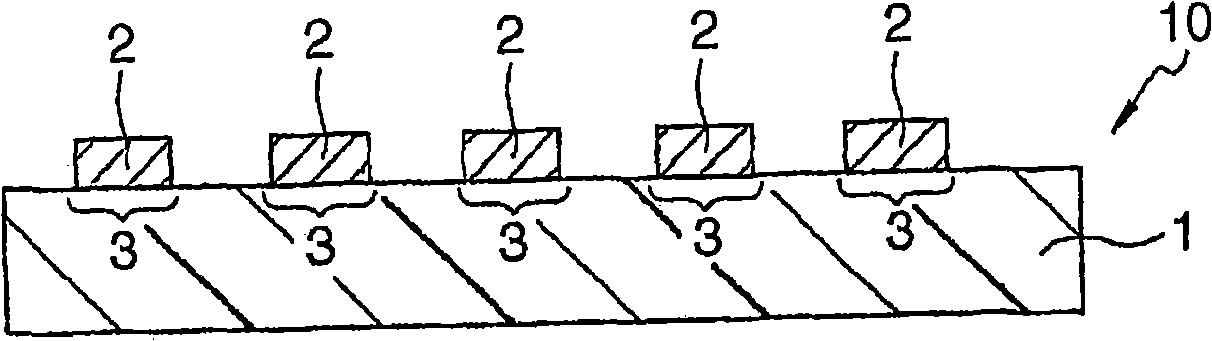
[0051] Projections were formed on the circuit surface of the flexible printed circuit board by pressing with a mold having the following form.

[0052] Die: SKD-11, commercially available from Ohtake Seisakusho K.K., Gifu-ken, Japan, comprising 8 linear grooves with 200 μm pitch, 30 μm height.

[0053] Pressing plate: wire bumps and flexible printed circuit board circuits are arranged orthogonally and pressed with a load of 4...


PUM

PropertyMeasurementUnit
diameteraaaaaaaaaa
softening pointaaaaaaaaaa
viscosityaaaaaaaaaa

Abstract

To provide a method for connecting printed circuit boards with high connection reliability, while avoiding the problem of shorting even with a fine pitch. A method for connecting printed circuit boards (PCB) containing metal wiring, or connecting a printed circuit board (PCB) containing metal wiring with a metal lead wire or a metal contact, which method includes a step of thermocompression bonding of an adhesive film with connectors, the adhesive film being composed of an adhesive composition comprising a thermoplastic resin and organic particles, wherein the viscosity decreases as the applied thermocompression force increases at a temperature of 100-250 DEG C.

Description

technical field [0001] The present invention relates to a method for connecting a printed circuit board (PCB) containing metal wiring (including flexible type and rigid type) or connecting a printed circuit board (PCB) containing metal wiring with metal leads or metal contacts (for example, in electrical Metal contacts in connectors) method. Background technique [0002] Methods utilizing soldering, anisotropic conductive adhesives, and mechanical connectors have been used in the past as electrical connection techniques for establishing connections between circuit boards. Soldering requires temperatures of 260°C and higher, and the surrounding assembled parts and even the circuit board itself sometimes cannot withstand such high temperatures. The assembly order and assembly position of parts must be considered so that parts with low thermal resistance are not exposed to heat, and this has reduced assembly density and limited the kinds of parts that can be assembled. Format...

Claims


Application Information

Patent Timeline
19 Nov 2008
Publication
CN101310573A
IPC
H05K3/36; H05K1/14
CPC
H05K2203/0285; H05K3/361; H05K2201/0129; H05K2201/0212; H05K2201/10977; H05K2203/1189; H05K3/328; H05K2203/0278
Inventors
川手恒一郎; 川手良尚