Constant-current driving circuit

A driving circuit and constant current technology, applied in the direction of electric lamp circuit layout, electric light source, electric light source, etc., can solve the problems of efficiency loss, voltage drop, etc., and achieve the effect of small efficiency loss

Active Publication Date: 2008-12-03
ITE TECH INC
View PDF0 Cites 16 Cited by
  • Summary
  • Abstract
  • Description
  • Claims
  • Application Information

AI Technical Summary

Problems solved by technology

The voltage of the output signal VOUT must be large enough to ensure the normal operation of the current source 111. However, when the forward bias voltage VF of the light emitting diode 120 changes due to process factors, or the current I Under the condition of being adjustable, the total cross-voltage of the light-emitting element string 121 may be smaller than the originally assumed total cross-voltage, but the voltage of the output signal VOUT is within the given fixed reference voltage FVREF, resistors 140 and 150 After that, the value has been fixed, so the output signal VOUT cannot be optimized for different light-emitting component strings 121, so that there is a redundant voltage drop on the current source 111, resulting in a loss in efficiency, and also in this constant current drive circuit. Unnecessary heat generation in 110

Method used


Image

  • Constant-current driving circuit
  • Constant-current driving circuit
  • Constant-current driving circuit

Examples


Embodiment Construction

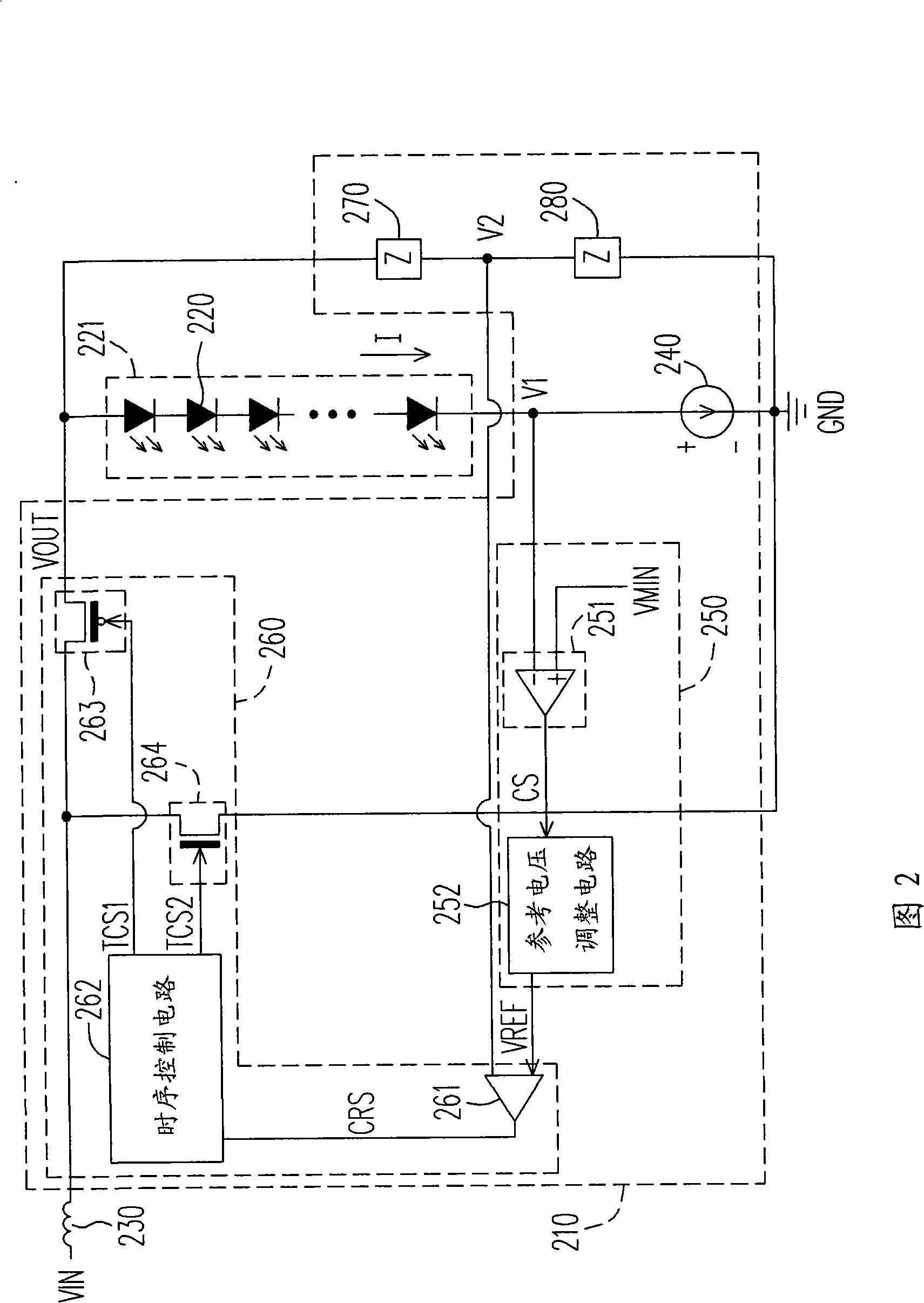
[0075] FIG. 2 is a schematic diagram illustrating the coupling of a constant current driving circuit driving a string of light emitting elements according to an embodiment of the present invention. 210 marked in the figure is a constant current driving circuit according to an embodiment of the present invention, which is used to drive a string of light emitting elements 221 formed by connecting light emitting diodes 220 in series. In addition, the constant current driving circuit 210 also receives the input signal VIN through the inductor 230 . The components included in the constant current driving circuit will be first described below, and the operation of each component will be briefly described.

[0076] The constant current driving circuit 210 includes a current source 240 , a reference voltage generating circuit 250 , an output signal generating circuit 260 , and impedances 270 and 280 . The impedances 270 and 280 are used to divide the output signal VOUT of the constan...


PUM


Abstract

The invention provides a constant current drive circuit which comprises a first current supply, a reference voltage generation circuit and an output signal generation circuit. One end of the first current supply is coupled with one end of a first light-emitting component series, wherein, the end of the first power supply is provided with a first voltage; the reference voltage generation circuit is used for generating reference voltage and compares the first voltage with a first preset voltage to generate a first comparison signal and dynamically adjust the value of the reference voltage according to the first comparison signal; the output signal generation circuit is used for outputting output signals to the other end of the first light-emitting component series and receiving input signals and determining whether to output the input signals according to the result of the comparison between the reference voltage and a second voltage so as to form the output signals.

Description

technical field [0001] The invention relates to a driving circuit, and in particular to a constant current driving circuit. Background technique [0002] FIG. 1 is a schematic diagram of the coupling of a conventional constant current driving circuit driving a string of light emitting elements. 110 marked in the figure is an existing constant current driving circuit, which is used to drive a string of light emitting elements 121 formed by connecting light emitting diodes (Light Emitting Diode, LED) 120 in series. In addition, the constant current driving circuit 110 also receives the input signal VIN through the inductor 130 , and divides the output signal VOUT through the resistors 140 and 150 to obtain a voltage VR, and then uses the voltage VR to perform feedback control. [0003] The constant current driving circuit 110 includes a current source 111 , a comparator 112 , a timing control circuit 113 , a PMOS (P-type metal oxide semiconductor) transistor 114 and an NMOS (...

Claims


Application Information

Patent Timeline
Patent Type & Authority Applications(China)
IPC IPC(8): H05B37/02F21S4/00F21Y101/02F21K9/20F21Y115/10
Inventor 周宜群陈许民
Owner ITE TECH INC
Why Eureka
Try Eureka