

Construction method of steel pipe concrete column
A technology for concrete-filled steel tubular columns and construction methods, which is applied to columns, piers, pillars, etc., can solve the problems of high pressure requirements of conveying pumps, large one-time pouring height, affecting concrete quality, etc., and achieves small shrinkage gap and quality assurance. , the effect of easy material processing
- Summary
- Abstract
- Description
- Claims
- Application Information
AI Technical Summary
Problems solved by technology
Method used
Image

Examples
Embodiment 1
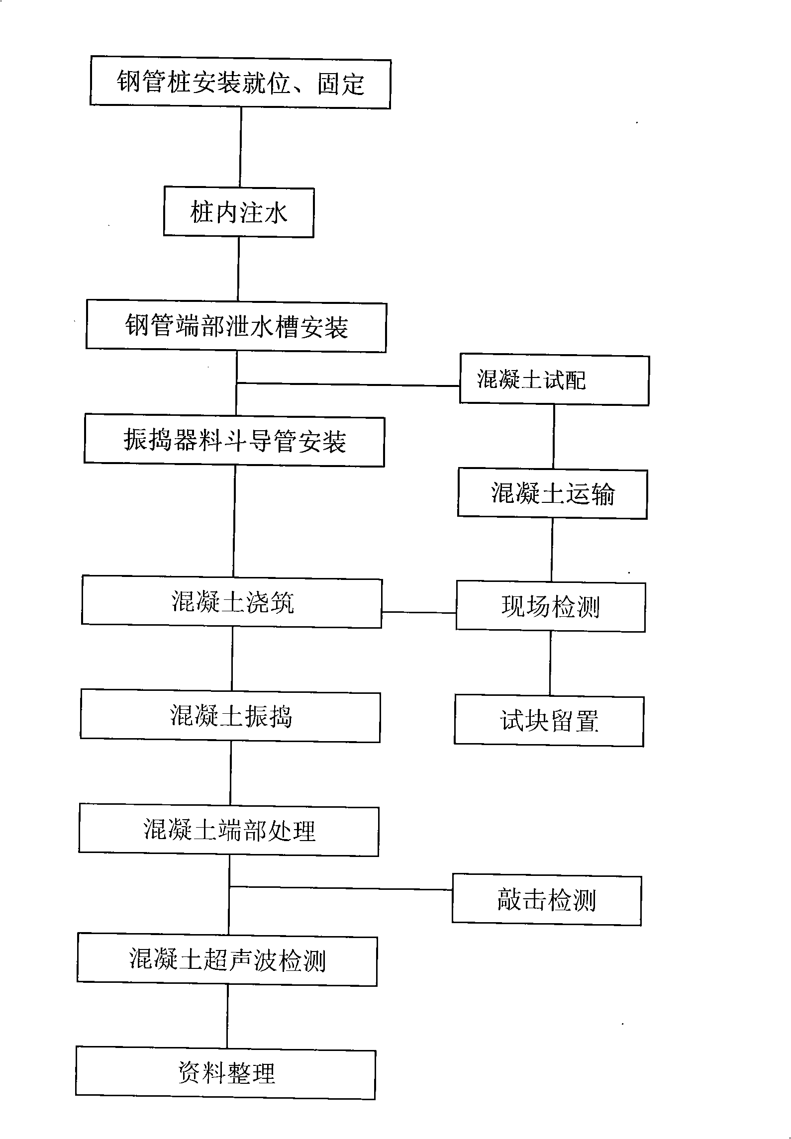
[0016] Press as figure 1 The technological process shown is for the construction of concrete-filled steel pipe columns. The 35-meter-high limb concrete-filled steel pipe concrete is poured diagonally. After the steel pipe piles are installed and the strength of the foundation concrete reaches 75%, the steel pipes are filled with water using a water pump. . use The 2-meter section of the steel pipe is connected with a screw, and the middle is a slipknot. Make a conduit. Insert the prepared conduit into the steel pipe at a distance of 600mm from the bottom of the steel pipe. The pressure reduces the falling speed of the concrete, pouring to 3 meters above the conduit at one time, lifting the conduit, and ensuring that the conduit is embedded in the concrete not less than 2 meters, and then pouring concrete for the second time. Start the vibrator outside the bottom pipe, the working range is effective when the transverse amplitude of the steel pipe is not less than 0.3mm, and ...
Embodiment 2
[0019] After the steel pipe piles are installed, a water pump is used to fill the steel pipes with water. The conduit connected to the bottom of the hopper is inserted into the steel pipe, 600mm away from the bottom of the steel pipe. After the concrete strength of the filling cup mouth reaches 75%, the hopper is used for concrete pouring. The conduit should be lifted slowly according to the falling speed of the concrete, and the lift of the conduit should be controlled by the amount of concrete. Speed, concrete vibration: After the first pouring, the concrete is embedded in the conduit for 2 meters, and the attached vibrator is started. The vibration time should be controlled within 1 minute to prevent segregation of the concrete caused by excessive vibration. The main function of vibration is to compact concrete and reduce air bubbles in concrete. Repeatedly in sequence, without stopping during the pouring process, the concrete is poured to the top of the column, the laitanc...
PUM
 Abstract
Description
Claims
Application Information