Eureka AIR delivers breakthrough ideas for toughest innovation challenges, trusted by R&D personnel around the world.

Construction method for paving composite veneer panel on external concrete wall of steel reinforced concrete buildings

A technology of reinforced concrete and construction method, which is applied in building structure, construction, covering/lining and other directions, can solve the problems of time-consuming, complicated, labor and time for chiseling and cleaning operations, etc., and achieves high strength, easy construction, Good workability

Inactive Publication Date: 2008-12-10
KK TESUKU +1
View PDF1 Cites 1 Cited by
  • Summary
  • Abstract
  • Description
  • Claims
  • Application Information

AI Technical Summary

Problems solved by technology

[0015] In addition, in order to allow the surface of the panel to be pasted flush regardless of the unevenness of the concrete frame surface, it is necessary to deal with the degree of flattening by pressing the lump adhesive. There is a limit to the absorption of unevenness on the surface of the concrete frame by the pushing deformation of the agent, and the work of making the pushing and flushing by hand from the surface side of the composite panel to the surface of the concrete frame requires labor and effort. It is manual and discrete work, so it is very difficult to paste composite panels flush
[0016] In addition, disposing a predetermined amount of adhesive at predetermined intervals on the surface of the concrete frame so that the lump-like adhesive is positioned at a predetermined position of the panel is also a troublesome work.
[0017] In addition, in the method of prior art example 1, when laying composite panels outside the existing concrete frame, since there are generally unevennesses on the surface of the concrete outer wall, it is necessary to use chisel work. The work of leveling the surface of the concrete exterior wall and the preparatory work for flushing and pasting composite panels are complicated, time-consuming and labor-intensive tasks
[0018] In addition, in the exterior laying method of prior art example 2 (FIG. 9), the pasting of the composite panels on the surface of the concrete frame is to adjust the agglomerates of the adhesive to the position where the composite panels need to be bonded, and arrange them in a dispersed manner. On the surface of the concrete frame, in order to bond the thermal insulation layer of the composite panel to the surface of the concrete frame, the unevenness of the surface of the concrete frame is dealt with by means of the pushing deformation of the agglomerate adhesive, and the surface of the concrete frame is repaired and chiseled as required Work, cleaning of the surface of the concrete frame, placement of agglomerated adhesives, etc. are complicated and labor-intensive and time-consuming tasks, and it is difficult to lay the composite panels flush with the outside

Method used

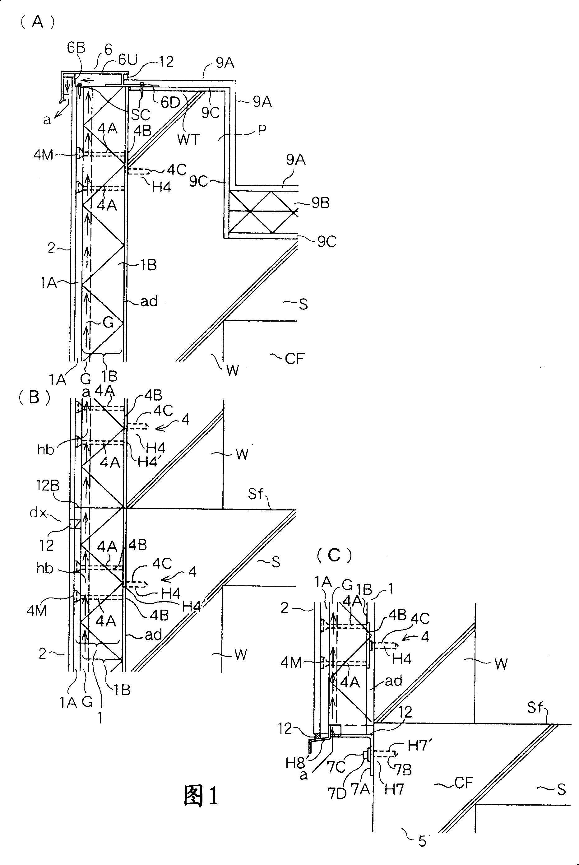
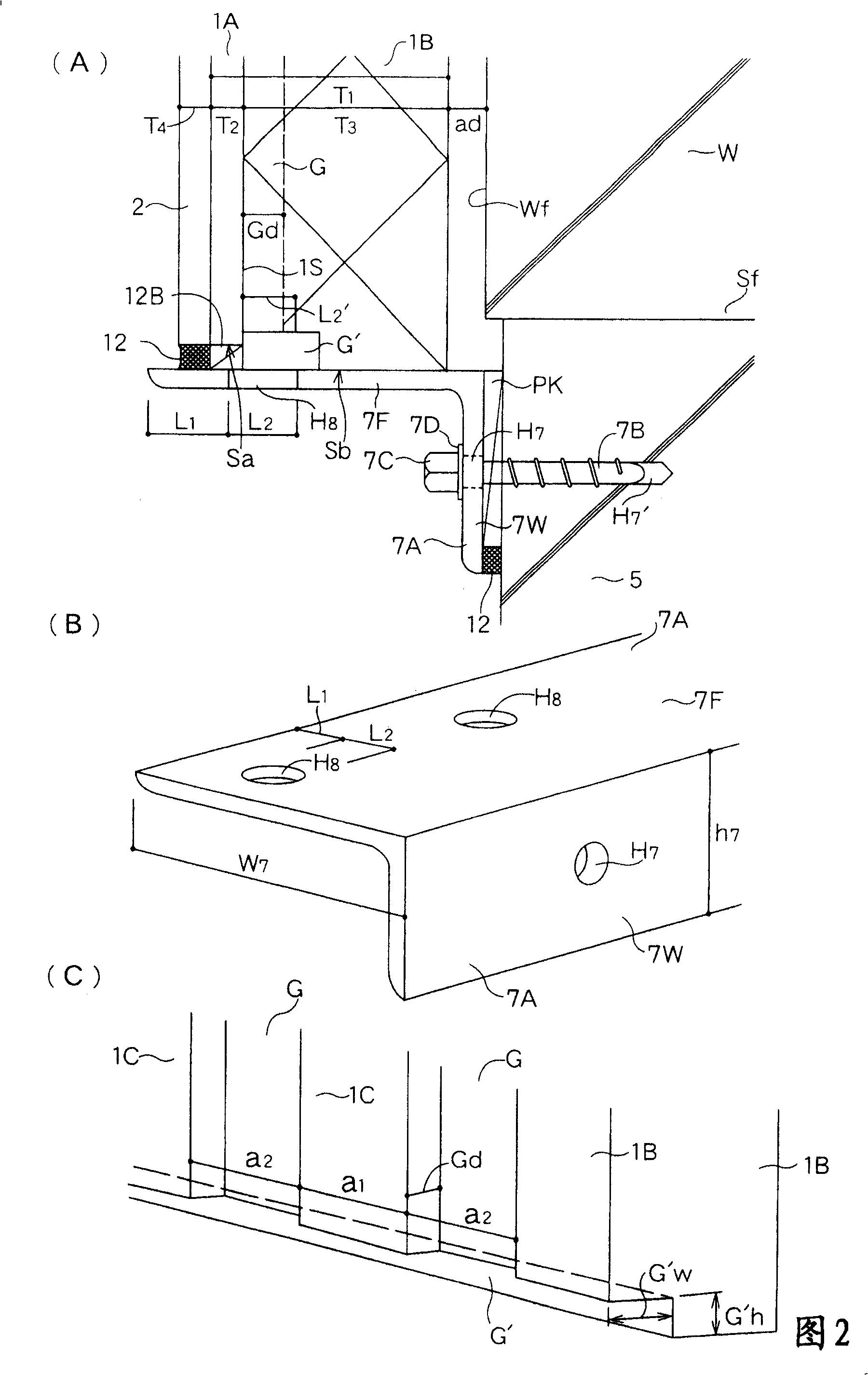
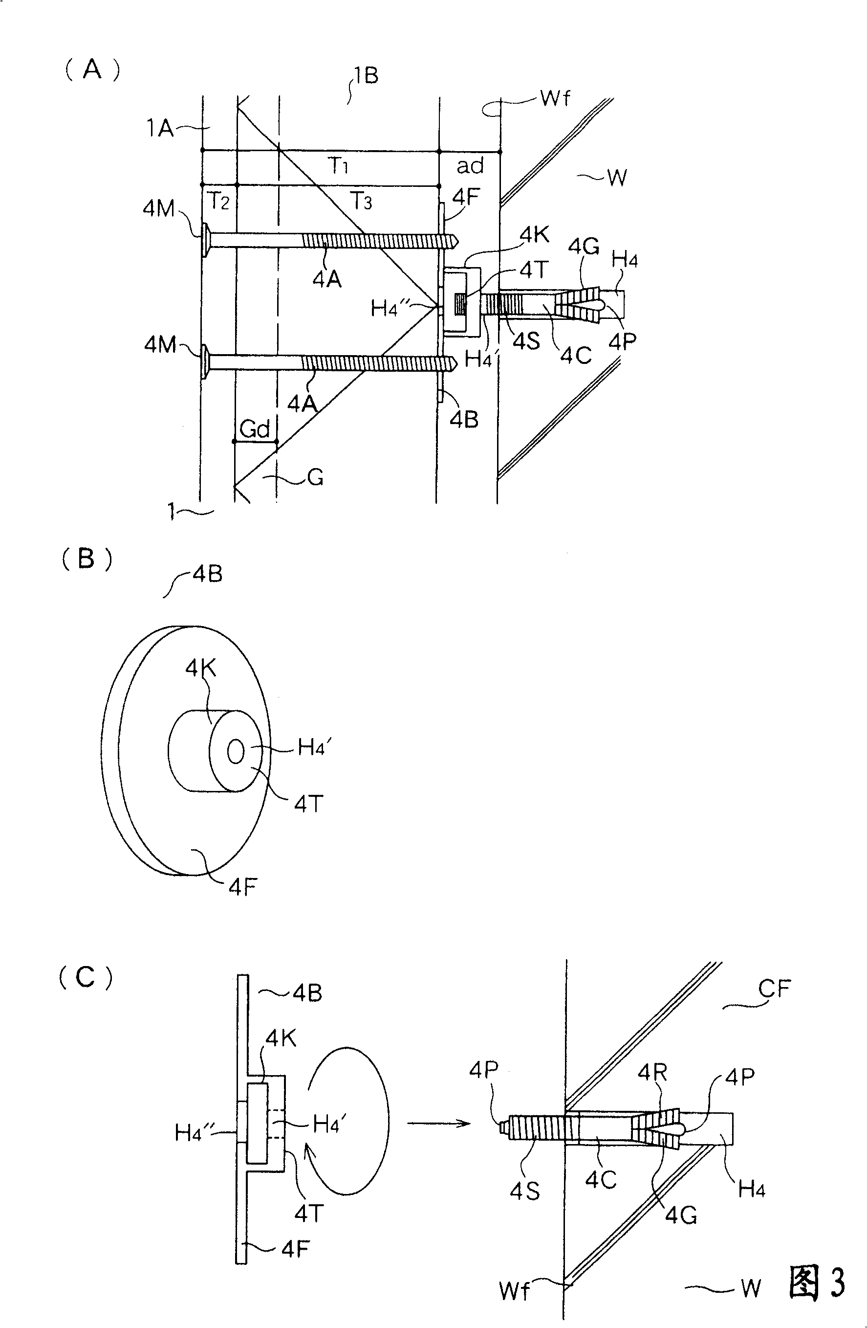

Image

  • Construction method for paving composite veneer panel on external concrete wall of steel reinforced concrete buildings
  • Construction method for paving composite veneer panel on external concrete wall of steel reinforced concrete buildings
  • Construction method for paving composite veneer panel on external concrete wall of steel reinforced concrete buildings

Examples


Deformed example 1

[0188] [Modification 1 (Fig. 6)]

[0189] Fig. 6 (A), (B) show the different implementation forms of the panel supporting hardware of the composite panel supporting the lowermost end, Fig. 6 (A) is the longitudinal sectional view of the use state, Fig. 6 (B) is the exploded perspective view .

[0190] The panel support hardware 11A is composed of a support angle R11 of equilateral angle steel with a horizontal piece 11F and a vertical piece 11W, and a steel flat plate 11U superimposed on the horizontal piece 11F of the support angle R11. Bolt holder insertion holes H7 are arranged on the vertical sheet 11W, and oval air holes H8 are arranged on the flat plate 11U.

[0191] In Modification 1, since the flat plate 11U is used mounted on the horizontal piece 11F supporting the angle steel R11, the mounting and fixing of the flat plate 11U on the horizontal piece 11F is free, and the front position of the lowermost panel 1 is changed. , that is, the dimensional change of the int...

Deformed example 2

[0192] [Modification 2( Figure 7 )]

[0193] Figure 7 It shows the installation method of the composite panel 1 which improves earthquake resistance and wind pressure resistance, Figure 7 (A) is a longitudinal sectional view, Figure 7 (B) is a view of (A) arrow B, Figure 7 (C) is a cross-sectional view in the case of using a short flat plate, Figure 7 (D) is Figure 7 (C) View of arrow D.

[0194] That is, if Figure 7 As shown in (B), the connecting plate 10A is further directly superimposed on the surface of the group of steel liners 4B that are screwed flush and fixed on the group of the rear driving fixture 4C, and the connecting plate 10A is fixed to the group with small screws 10S. Pad 4B on flat disc 4F.

[0195] The connecting plate 10A can adopt a steel plate with a thickness of 2.3 mm and a width of 80 mm, and the interconnected and integrated gaskets 4B of the connecting plate 10A can exert uniform panel supporting force.

[0196] In this case, the st...


PUM


Abstract

The project of the invention is to levelly paste a heat-insulated composite panel board without use of binder and having no relation with irregularity of concrete outer wall in the outer laying method of concrete external wall of reinforced concrete building that is externally laid by cemented layered composite panel board. The solution is: a composite panel board (1) is supported by means of being fixed to the angle-shaped panel board support hardware (7A) on a concrete framework (CF). The mode of laying composite panel board (1) on the concrete external wall (W): driving a rear drive fixer (4C) with a screw thread surface (4S) at the rear periphery into the concrete external wall (W), connecting a projecting steel pad (4B) of a projection (4K) with screwed hole (H4) to the screw thread surface (4S) of the rear drive fixer (4C) rear, measuring a flat pan (4F) of each steel pad (4B) when processing level positioning so as to contact the inner surface of each composite panel board (1) with the flat pan (4F) of each steel pad (4B); levelly configuring; screwing a long bolt (4A) from the surface; fixing each composite panel board (1) to the steel pad (4B).

Description

technical field [0001] The present invention relates to a construction method for laying dry-type heat-insulating composite panels on the concrete exterior wall of a reinforced concrete building. Whether the wall is uneven or not, and a construction method capable of laying heat-insulating composite panels flushly on the concrete outer wall, belong to the field of building technology. Background technique [0002] External heat insulation buildings made of reinforced concrete, because the outer side of the concrete frame is covered with a heat insulating layer, so the cracking of the reinforced concrete caused by the thermal stress of the sun can be suppressed, and since the concrete frame does not come into contact with the outside air, It can inhibit the neutralization effect of concrete, can inhibit the corrosion of steel bars, and improve the durability of buildings. Furthermore, since the outer surface of the entire building is covered with a heat-insulating layer, it i...

Claims


Application Information

Patent Timeline
IPC IPC(8): E04F13/21
Inventor 丹征吉樱庭高光
Owner KK TESUKU
Why Eureka
Eureka Blog
Learn More