
Method and equipment for optical fibre optical grating sensing array demodulation

A sensing array and fiber grating technology, applied in light demodulation, using optical devices to transmit sensing components, cladding optical fibers, etc., can solve the problem of high cost of FBG sensing network, limited practical application, and high cost of light source Demodulation system and other issues

Inactive Publication Date: 2008-12-10
ZHEJIANG UNIV
View PDF0 Cites 7 Cited by
  • Summary
  • Abstract
  • Description
  • Claims
  • Application Information

AI Technical Summary

Problems solved by technology

Both sets of multiplexing technologies require high-cost light sources and complex demodulation systems, which directly lead to the high cost of the FBG sensor network and limit many of its practical applications.

Method used


Image

  • Method and equipment for optical fibre optical grating sensing array demodulation
  • Method and equipment for optical fibre optical grating sensing array demodulation
  • Method and equipment for optical fibre optical grating sensing array demodulation

Examples


Embodiment Construction

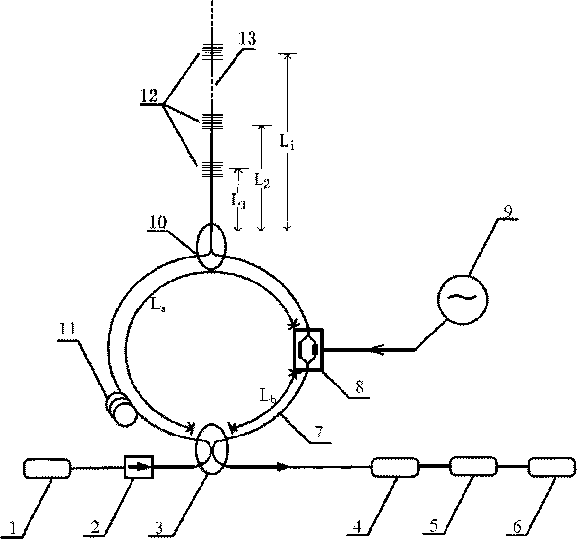
[0031] Such as figure 1 As shown, the semiconductor laser 1 is optically connected to one input port of the four-port 3-dB fiber coupler 3 through the fiber isolator 2; the other input port of the four-port 3-dB fiber coupler 3 is optically connected to the input end of the photodiode 4 In connection, the output end of the photodiode 4 is electrically connected to the input end of the data acquisition card 5, and the output end of the data acquisition card 5 is electrically connected to the FFT analyzer 6. The two output ports of the four-port 3-dB optical fiber coupler 3 are connected by a single-mode fiber. The single-mode fiber is divided into two sections by the electro-optic modulator 8. They are the measurement section single-mode fiber 11 and the connecting section single-mode fiber 7, respectively. Respectively L a And L b , L a >>L b . The electrical drive signal port of the electro-optical modulator 8 is electrically connected to the sinusoidal signal generator 9. A thr...


PUM


Abstract

The invention relates to a method and a device for demodulating a fiber bragg grating sensor array. In the invention, a continuous semiconductor laser with narrow line width is used as an optical source; an electro-optic modulator is connected with a Sagnac loop; an FBG sensing array is connected with the Sagnac loop by a three-port 3-dB fiber coupler; the bragg wavelengths of each sensing FBG connected in series on the sensing array under the room temperature are consistent with the central wavelength of the laser optical source; besides, the reflection rates are all less than 3 percent; the electro-optic modulator is driven by a RF signal the frequencies of which can be modulated; the change of the transmittance is detected by a low-speed photodiode; the drift amount of the bragg wavelengths of each sensing FBG on the sensing array is obtained by carrying out fast Fourier transformation and relevant operations on the data collected by a collecting card, and finally the change of the sensed physical quantity is obtained. The invention can have an extremely high response speed for meeting the requirements of real time sensing and has a relative lower cost; besides, as the sensing array is connected with the Sagnac loop, the performances of anti-external temperature fluctuation and anti-mechanical disturbance of the device are high.

Description

Technical field [0001] The invention belongs to the field of optical fiber sensing technology, and is suitable for the field of real-time sensing networks that require quasi-distributed, high-precision, and anti-electromagnetic interference. In particular, it relates to a new method of using electro-optic modulators to change the frequency of light waves to cause the asymmetry of the Sagnac ring structure and fiber Bragg grating (FBG) hypotenuse detection technology to achieve demodulation of FBG sensor arrays and The equipment that implements the method. Background technique [0002] FBG has become an important device for optical fiber sensing due to its unique advantages of optical fiber internal sensitivity, wavelength coding, and easy networking. Based on the developed wavelength division multiplexing (WDM) and time division multiplexing (TDM) technologies, fiber grating arrays are widely used in optical fiber quasi-distributed sensing, such as: health monitoring of railways,...

Claims


Application Information

Patent Timeline
IPC IPC(8): G01D5/353G02B6/02G02B6/28G02F2/02G02F1/03
Inventor 何赛灵周斌刘伟升
Owner ZHEJIANG UNIV
Learn More