Tank-carrying hydraulic automatic discharging vehicle

A loading and unloading truck and hydraulic technology, which is applied in the direction of tilting and carrying vehicles

Inactive Publication Date: 2008-12-17
刘景田
View PDF0 Cites 2 Cited by
  • Summary
  • Abstract
  • Description
  • Claims
  • Application Information

AI Technical Summary

Problems solved by technology

[0003] The purpose of the present invention is to provide a back-tank hydraulic automatic loading and unloading vehicle t

Method used


Image

  • Tank-carrying hydraulic automatic discharging vehicle
  • Tank-carrying hydraulic automatic discharging vehicle
  • Tank-carrying hydraulic automatic discharging vehicle

Examples


Embodiment Construction

[0009] In order to further disclose the technical solutions of the present invention, the following will be described in detail through examples in conjunction with the accompanying drawings:

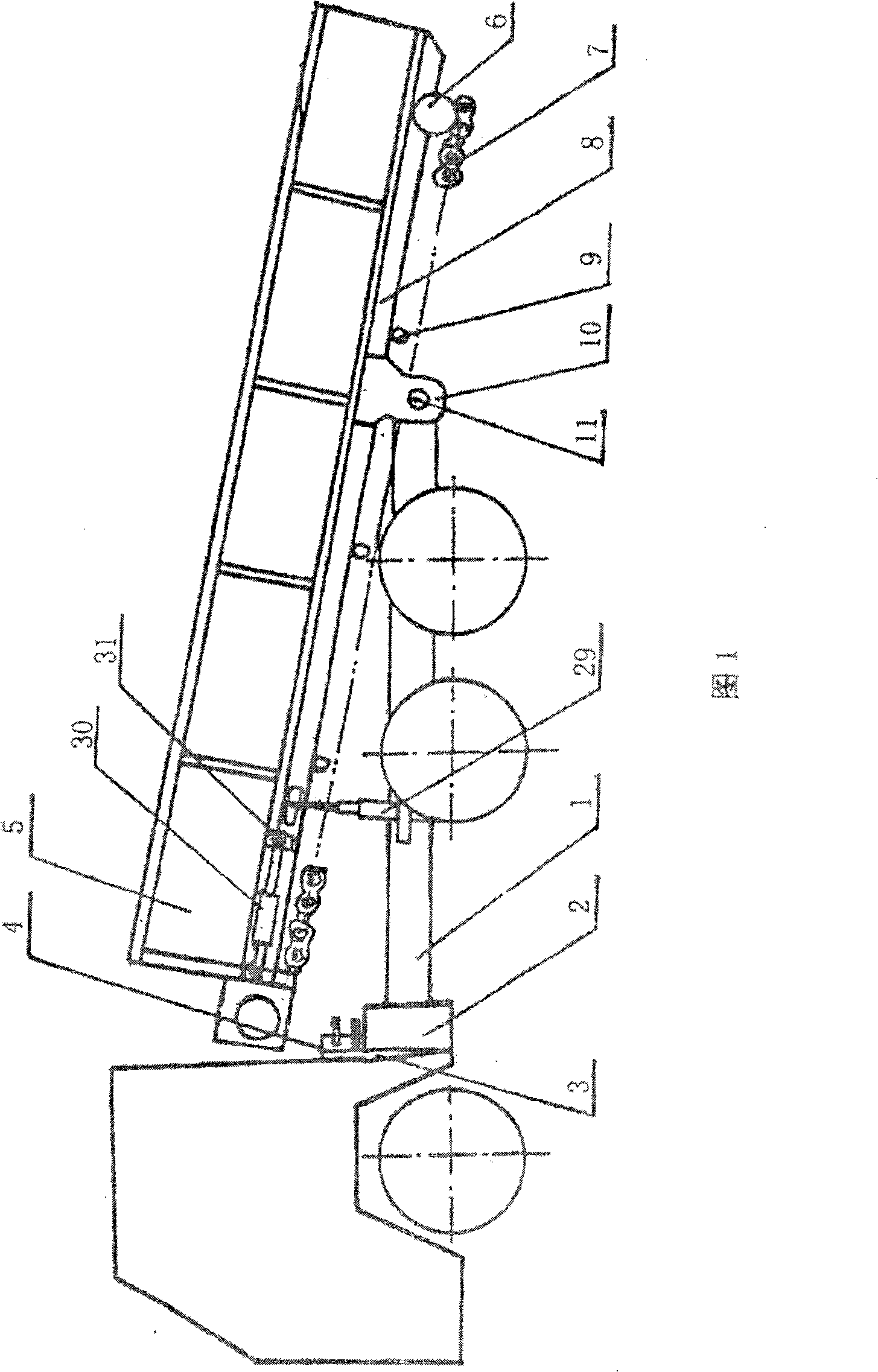
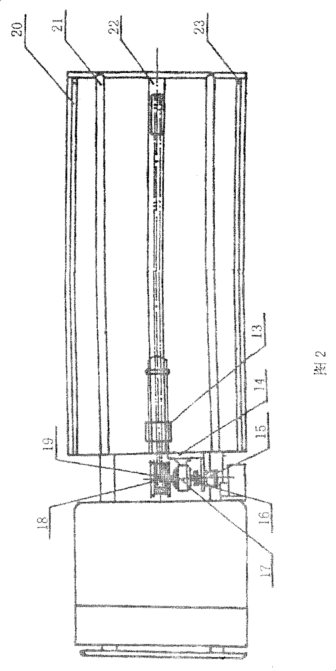
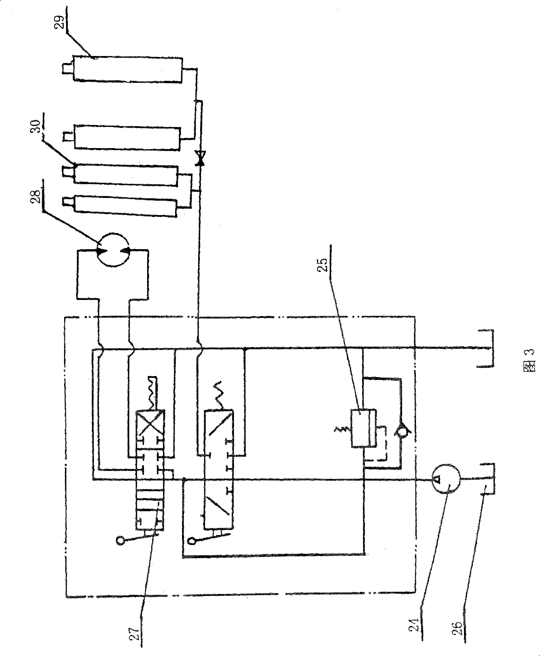
[0010] The automatic back tank loading and unloading truck is composed of a carriage guiding system, a chain transmission system and a hydraulic transmission system connected thereto. When the tank car is working, the hydraulic oil pump 24 distributes the power fluid to the carriage hydraulic cylinders 29 and 30 through the hydraulic reversing valves 4 and 27, the hydraulic pistons stretch out, the movable carriage moves forward and the rear end rises and the tail contacts the ground. The power fluid to the valves 4 and 27 enters the hydraulic oil motors 15 and 28 in different directions to realize forward and reverse rotation. Move forward with the wire rope hanger 13, and the tank body hung with the wire rope hanger 13 runs to the front end of the movable carriage at the same time, un...


PUM


Abstract

A knapsack hydraulic automatic lift truck adopts a truck model with strong cross-country performance. A moveable vehicle body and a hydraulic loading and unloading transmission system are added on a second class chassis; a groove plate of the vehicle body is welded with a chain guide groove; the integration of the knapsack loading and knapsack unloading can be realized by the hydraulic transmission of the chain. Therefore, the working efficiency and safety factor are increased; the speed of the specialization of the logistic mechanical matching in oilfield developing operation is improved; the labor intensity of workers is decreased.

Description

1. Technical field [0001] A back-tank hydraulic automatic loading and unloading truck, which belongs to petroleum mine machinery, is especially used for relocation of movable tanks used in oil field drilling and workover operations, and can also be used for relocation of bridge-mounted movable houses and bridge-mounted movable machinery. construction. 2. Background technology [0002] At present, in the process of petroleum development, the transportation of water tanks or oil tanks used in drilling and workover operations is mostly carried by trucks, loaded and unloaded by cranes, and trailers or tractors are required in rainy seasons. Therefore, the accidents of towed cranes and damaged trucks occur from time to time, which affect the normal progress of drilling and workover work. These tanks are generally used to store waste liquid or dirty oil and sewage in the process of drilling and workover operations. During construction in the summer rainy season, the well site is ...

Claims


Application Information

Patent Timeline
IPC IPC(8): B60P1/16
Inventor 刘冰刘景田
Owner 刘景田
Why Eureka
Try Eureka