Brake control unit for locomotive electro-pneumatic brake

An electro-pneumatic braking and braking control technology, which is applied to vehicle control route devices, railway car body components, railway signals and safety, etc. Fault information and other issues, to achieve the effect of improving handling performance and safety, good stability and anti-interference, and improving safety

Active Publication Date: 2008-12-17
ZHUZHOU ELECTRIC LOCOMOTIVE CO
View PDF0 Cites 39 Cited by
  • Summary
  • Abstract
  • Description
  • Claims
  • Application Information

AI Technical Summary

Problems solved by technology

Existing domestic electric locomotives generally use the DK-1 locomotive electro-pneumatic brake, and its brake control unit has the following deficiencies: 1. It can only perform logic control operations; 2. It cannot collect analog values. The pressure of the cylinder can only be controlled in an open loop; 3. It does not have

Method used


Image

  • Brake control unit for locomotive electro-pneumatic brake
  • Brake control unit for locomotive electro-pneumatic brake
  • Brake control unit for locomotive electro-pneumatic brake

Examples


Embodiment Construction

[0060] The present invention will be described in further detail below in conjunction with the accompanying drawings and specific embodiments.

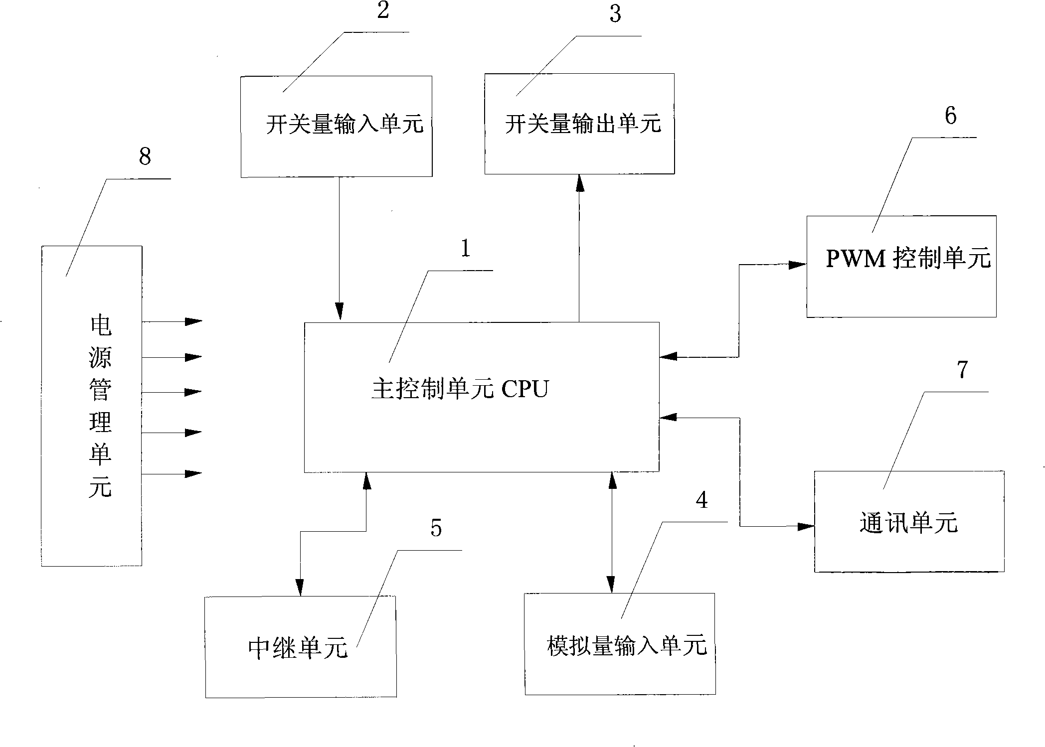
[0061] Such as figure 1 As shown, a brake control unit for locomotive electro-pneumatic brakes of the present invention includes a main control unit 1, a switch input unit 2, a switch output unit 3, an analog input unit 4, and a relay unit 5. The PWM drive unit 6, the communication unit 7 and the power management unit 8 for supplying power to the above-mentioned components, the switching value input unit 2 for inputting the digital control signal is connected to the input terminal of the main control unit 1 for outputting the digital control signal The switch value output unit 3 is connected to the output end of the main control unit 1, the main control unit 1 controls the pressure of the balance air cylinder 9 and the brake air cylinder 10 of the electric control motor through the PWM drive unit 6, and the main control unit 1 passes ...


PUM


Abstract

The invention discloses a brake control unit for a locomotive electro-pneumatic brake, which comprises a main control unit, a switching value input unit, a switching value output unit, an analog value input unit, a relay unit, a PWM control unit, a MVB communication unit and a power management unit supplying power for all the components; wherein, the switching value input unit used for inputting digital control signals is connected with an input terminal of the main control unit; the switching value output unit used for outputting digital control signals is connected with an output terminal of the main control unit; the main control unit controls the pressure of an equalizing reservoir and a braking reservoir of the electro-pneumatic brake by the PWM control unit; the main control unit is connected with peripheral equipment for communication by the communication unit and collects current signals sent by a sensor by the analog value input unit. The brake control unit has the advantages of simple and compact structure, high cost performance, etc. The functions of microcomputer control and network communication help the brake control unit improve control accuracy and enlarge application range.

Description

technical field [0001] The invention mainly relates to the field of brake control systems in railway locomotives, in particular to a brake control unit for locomotive electro-pneumatic brakes. Background technique [0002] At present, railway locomotives are developing in the direction of high speed and heavy load. This development trend puts forward higher requirements for the train brake control system. Existing domestic electric locomotives generally use the DK-1 locomotive electro-pneumatic brake, and its brake control unit has the following deficiencies: 1. It can only perform logic control operations; 2. It cannot collect analog values. The pressure of the cylinder can only be controlled in an open loop; 3. It does not have the function of fault diagnosis and data dump, and cannot provide relevant locomotive fault information to the driver or ground maintenance personnel when a fault occurs; 4. It does not have the network communication function, so it cannot be comple...

Claims


Application Information

Patent Timeline
IPC IPC(8): B61L3/00
Inventor 刘豫湘刘泉高殿柱方长征邓李平
Owner ZHUZHOU ELECTRIC LOCOMOTIVE CO
Why Eureka
Try Eureka