Projector

A technology for projectors and optical components, applied in the field of projectors, can solve the problems of increasing the power consumption of circulating fans, difficult cooling of light modulation devices, and easy retention of cooled air between thermoelectric conversion elements and light modulation devices, etc., to achieve increased Surface area, heat degradation prevention, good heat dissipation effect

Inactive Publication Date: 2008-12-17
SEIKO EPSON CORP
View PDF1 Cites 12 Cited by
  • Summary
  • Abstract
  • Description
  • Claims
  • Application Information

AI Technical Summary

Problems solved by technology

[0006] However, inside the sealed structure, since the light modulation device is provided between the thermoelectric conversion element and the circulation fan, the circulation fan sucks in the air near the light modulation device and sends the air cooled by the heat-absorbing surface of the thermoelectric conversion element to the When the light modulation device is used, the cooled air tends to stay between the thermoelectric conversion element and the light modulation

Method used


Image

  • Projector
  • Projector
  • Projector

Examples


no. 1 Embodiment approach

[0068] Hereinafter, a first embodiment of the present invention will be described with reference to the drawings.

[0069] [1. Appearance composition]

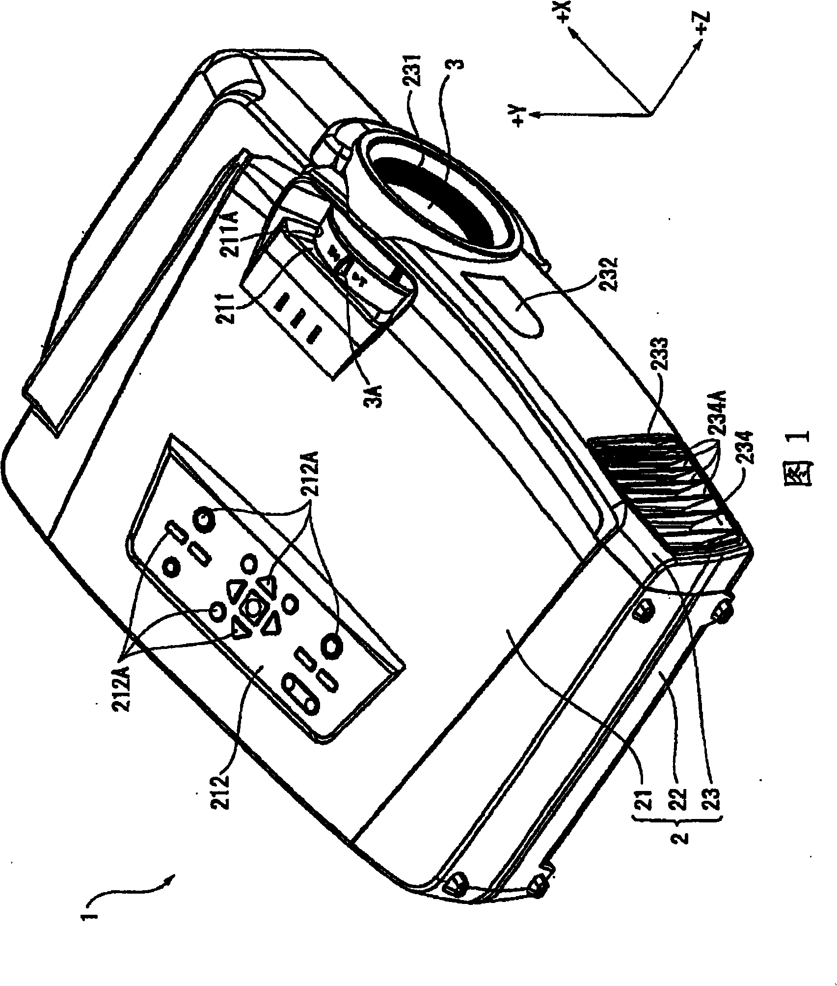
[0070] FIG. 1 is a perspective view showing the appearance of a projector 1 according to the first embodiment. Specifically, FIG. 1 is a perspective view of the projector 1 viewed from the upper front side. In addition, in FIG. 1 , for convenience of description, the projection direction of the optical image is referred to as the Z axis, and two axes perpendicular to the Z axis are referred to as the X axis (horizontal axis) and the Y axis (vertical axis). The same applies to subsequent drawings.

[0071] The projector 1 modulates light beams emitted from a light source according to image information to form an optical image, and enlarges and projects the formed optical image on a screen (not shown). As shown in FIG. 1 , the projector 1 has a substantially rectangular parallelepiped outer case 2 and a projection lens 3 as a...

no. 2 Embodiment approach

[0245] Next, a second embodiment of the present invention will be described with reference to the drawings.

[0246] In the following description, the same structures and members as those of the first embodiment described above are denoted by the same symbols, and their detailed descriptions are omitted or simplified.

[0247] FIG. 23 is a block diagram schematically showing the control structure of the Peltier element 7113 according to the second embodiment.

[0248] The difference of this embodiment from the aforementioned first embodiment is that, as shown in FIG. An internal air temperature detection unit 65 for detecting the temperature of the air circulating inside the sealed structure. Other structures are the same as those of the first embodiment described above. In addition, the inside air temperature detection part 65 may be arrange|positioned in any place as long as it is located in the position which can detect the temperature of the air which circulates inside a...

no. 3 Embodiment approach

[0269] Next, a third embodiment of the present invention will be described with reference to the drawings.

[0270] In the following description, the same structures and members as those of the second embodiment described above are denoted by the same symbols, and their detailed descriptions are omitted or simplified.

[0271] FIG. 26 is a block diagram schematically showing the control structure of the Peltier element 7113 according to the third embodiment.

[0272] This embodiment differs from the second embodiment described above only in the configuration of a Peltier control unit 61B as a control device for controlling a Peltier element 7113 as shown in FIG. 26 . Other structures are the same as those of the second embodiment described above.

[0273] As shown in FIG. 26 , the Peltier control unit 61B includes a voltage switching control unit 615 and a memory 613B in addition to the rectangular control unit 611 described in the first embodiment.

[0274] The voltage swit...


PUM

PropertyMeasurementUnit
Thermal conductivityaaaaaaaaaa

Abstract

The invention provides a projector (1) which comprises optical components arranged inside a sealed structure with an annular ventilation path, and a circulating fan (72) for cycling the air in the ventilation path. The sealed structure comprises a optical component used case body (46) with a inlet for air to flow inside and an outlet for air to flow outside; a plurality of air duct components used for leading air into the optical component used case body (46) and leading the air which flows out of the case body into the optical component used case body (46) again; and a cooling device (71) with thermoelectric conversion components. The cooling device (71), the circulating fan (72) and the optical component used case body (46) are sequentially arranged in the ventilation direction in the ventilation path. The air duct component (73) arranged at the front part of the ventilation path in the air duct components is made of a material with the thermo-conductivity less than or equal to 0.9W/ (m*K).

Description

technical field [0001] The present invention relates to projectors. Background technique [0002] Conventionally, there is known a projector that includes a light source device, a light modulation device that modulates a light beam emitted from the light source device according to image information to form an optical image, and a projection optical device that magnifies and projects the optical image. [0003] In this projector, if dust, soot, etc. adhere to the surface of the light modulation device, the image quality of the projected image will deteriorate. In addition, light modulating devices such as liquid crystal panels generally have poor heat resistance, and therefore may suffer thermal degradation due to heat generated by light beam irradiation from the light source device. [0004] Therefore, in order to stably ensure the image quality of the projected image and effectively cool the light modulation device, a structure has been proposed in which the light modulati...

Claims


Application Information

Patent Timeline
IPC IPC(8): G03B21/16G03B21/00H05K7/20G05D23/19
Inventor 柳沢佳幸百濑泰长
Owner SEIKO EPSON CORP
Why Eureka
Try Eureka