Gas pipeline drag reducer and preparation thereof

A gas pipeline and drag reducing agent technology, applied in the field of polymer compound compositions and pipeline systems, can solve the problems of limited drag reduction effect, etc., and achieve the effects of low equipment requirements, simple operation and mild reaction conditions

Inactive Publication Date: 2008-12-24
PETROCHINA CO LTD
View PDF1 Cites 42 Cited by
  • Summary
  • Abstract
  • Description
  • Claims
  • Application Information

AI Technical Summary

Problems solved by technology

However, although this patent proposes a method of applying drag reducers in gas pipelines and mentions some drag reducer substances, these substances have limited drag reduction effects and are not ideal drag reducers.

Method used


Image

  • Gas pipeline drag reducer and preparation thereof
  • Gas pipeline drag reducer and preparation thereof
  • Gas pipeline drag reducer and preparation thereof

Examples


Embodiment 1

[0024] Embodiment 1. This example is a test method in a laboratory. Specifically, 20 parts of hexadecanoic acid are added into a four-necked flask, and 10 parts of diethylenetriamine are injected after heating and melting. Under nitrogen protection, the temperature was slowly raised to 140°C. Then the temperature was programmed slowly, from 140°C to 220°C within 4 hours. Then connect the vacuum pump, evacuate for 3 hours, and the vacuum degree is 20mmHg. The resulting crude product is recrystallized from ethanol to obtain the product.

Embodiment 2

[0025] Embodiment 2. 36 parts of long-chain acids are added into a four-necked flask, and 20 parts of enamines are injected after heating and melting. Under nitrogen protection, the temperature was slowly raised to 140°C. Subsequently, the temperature was programmed slowly according to the above-mentioned heating method, and the temperature was programmed from 140°C to 210°C within 5 hours. Then connect the vacuum pump and vacuumize for 2 hours. The vacuum degree is 25mmHg. The resulting crude product is recrystallized from ethanol to obtain the product.

Embodiment 3

[0026] Embodiment 3. 54 parts of long-chain acids are added into a four-necked flask, and 30 parts of diethylenetriamine are injected after heating and melting. Under nitrogen protection, the temperature was slowly raised to 140°C. Subsequently, the temperature was programmed slowly according to the above-mentioned heating method, from 140° C. to 215° C. within 5 hours. Then connect the vacuum pump and vacuumize for 3 hours. The vacuum degree is 20mmHg. The resulting crude product is recrystallized from ethanol to obtain the product.

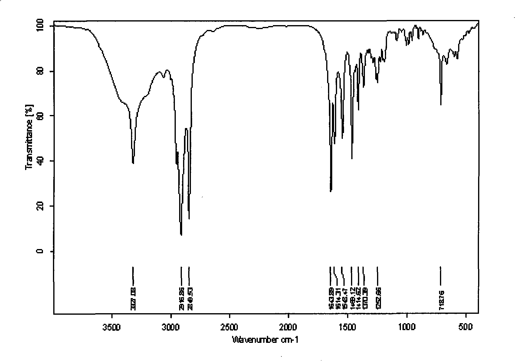
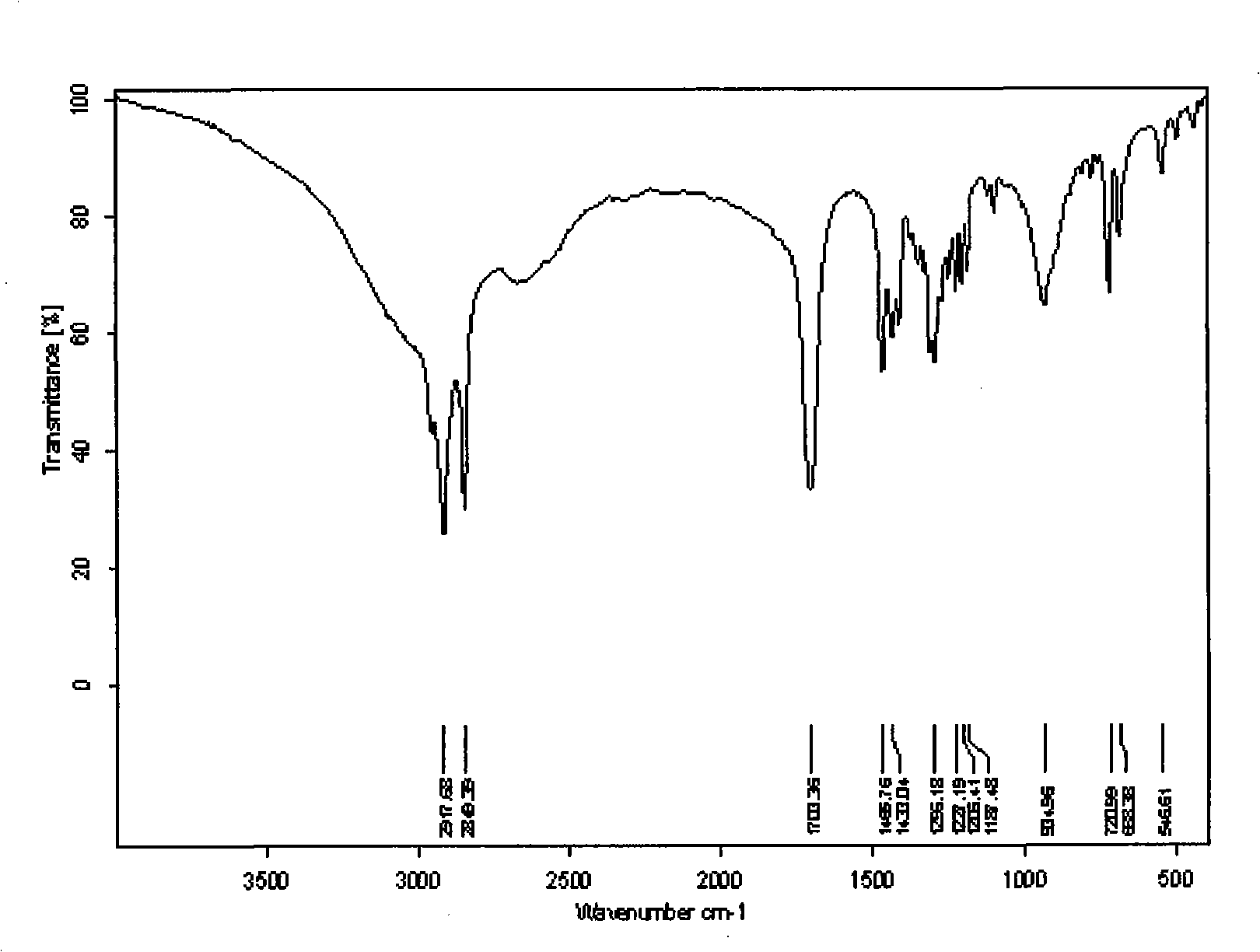
[0027] Above-mentioned three example gained drag reducers are done infrared spectrum analysis through laboratory, figure 1 In the infrared spectrum of the synthesized product, 2916.86cm -1 It is the C-H asymmetric stretching vibration in methylene, 2849.53cm -1 It is C-H symmetrical stretching vibration, and the in-plane rocking vibration of -CH2- in multi-carbon linear alkanes is at 718.16cm -1 There is absorption nearby, 1469.12cm -1 It...


PUM


Abstract

The invention relates to a gas pipeline drag reducer used in gas and particularly natural gas conveying pipeline drag reduction and a preparation method thereof, relating to a macromolecular compound composition and the pipeline system technical field. The gas pipeline drag reducer is characterized in that: the drag reducer is synthesized by long-chain acid and enamine according to a molar ratio of between 1:1 and 2.2:1. The preparation method comprises the following steps that: the long chain acid in proportional quantity is added in a reaction container; a heater is started so as to carry out heating while stirring; when temperature reaches to 100 DEG C, the long chain acid is melted, and the enamine in proportional quantity is added at the same time; nitrogen is fed in to carry out protection, and the mixture is preheated to between 120 and 140 DEG C; after preheating is finished, programmed heating is carried out till temperature is increased to between 210 and 220 DEG C; a stirrer is removed and a vacuum pump is connected to carry out evacuation for 2 to 4 hours; when reaction is finished, brown solid crude product can be obtained after cooling down. The gas pipeline drag reducer has obvious drag reduction effect on gas pipelines, direct source of raw materials, simple operation, moderate reaction conditions, relatively simple process and low requirements on equipment, and is easy to realize large-scale industrialized production.

Description

technical field [0001] The invention relates to a gas pipeline drag reducer for drag reduction of gas, especially natural gas pipelines, and a preparation method thereof. It relates to the technical field of polymer compound composition and pipeline system. Background technique [0002] The utilization of natural gas energy is one of the important development directions at home and abroad. Due to the global requirements for sustainable economic development and the call for "clean energy", the demand for natural gas is increasing day by day. [0003] At present, the main transportation mode of natural gas is pipeline transportation. Gas pipelines in the modern sense have a history of nearly 120 years. As the gas flows through the pipe, the roughness causes friction which in turn creates a gas vortex, causing energy loss and thus pressure loss in the pipe. For natural gas pipeline transportation in a state of turbulent flow, the pipe wall roughness has the greatest influen...

Claims


Application Information

Patent Timeline
Patent Type & Authority Applications(China)
IPC IPC(8): C10M105/60F17D1/02C10M105/22C10N50/02
Inventor 李春漫刘兵鲍旭晨李国平张志恒
Owner PETROCHINA CO LTD
Why Eureka
Try Eureka