Vertical conveyance device

A technology for handling devices and moving rails, which is applied in the fields of transportation and packaging, electrical components, semiconductor/solid-state device manufacturing, etc. It can solve the problems of lifting height limitation of rack-type lifting devices, reduced handling efficiency, low efficiency, etc., and achieves simple structure, Improvement of handling efficiency and expansion of production scale

Inactive Publication Date: 2008-12-24
MURATA MASCH LTD
View PDF2 Cites 27 Cited by
  • Summary
  • Abstract
  • Description
  • Claims
  • Application Information

AI Technical Summary

Problems solved by technology

However, as an example of the prior art, in the above-mentioned elevators with a conveying function of Patent Document 1 and Patent Document 2, no matter what the occasion, the conveying direction of the conveyor belt equipped on the elevator is always fixed, and it is along the floor of the receiving article. The conveying direction of the conveyor belt laid on the upper floor is always consistent with the conveying direction of the conveyor belt laid on the floor where the goods are handed over. In terms of considering the conveying direction, there are not all settings according to uniform specifications and the failure to construct the conveying track line. The problem
That is, the lifter related to the prior art cannot be applied to a conveying system of a conveyor belt conveying method using conveying tracks with various conveying directions, and also cannot adapt to changes in the conveying direction of the conveying tracks as the scale of the conveying system expands. The problem
In addition, by assembling the reloading machine (reloading robot, etc.) used for reloading articles on the vertical conveying device, although it can be adapted to the conveying system with conveying and conveying tracks in various conveying directions between multiple floors, the conveying capacity of the reloading machine is relatively large. Low, unable to coordinate with the high conveying capacity of the conveyor belt conveying method, there is a problem of becoming an inefficient conveying system
[0008] In addition, in the transportation system that uses transportation methods other than the conveyor belt transportation method to carry objects between floors, for example, there is a limitation in the lifting height of the rack lifting device, which leads to the problem that it cannot adapt to the transportation system composed of multiple floors.
In addition, although the stacker lifter is a transfer device that can be moved up and down freely without being restricted by the height direction, there is a problem that a transfer machine such as a transfer robot is required to transfer articles, and the transfer time of the transfer machine becomes a cause of reduction in transfer efficiency between floors.
Furthermore, in the vertical transfer device of the prior art, the transfer device is used in the elevator equipped with the transfer device, and since it takes time to transfer the articles, the transfer efficiency between floors cannot be improved.

Method used


Image

  • Vertical conveyance device
  • Vertical conveyance device
  • Vertical conveyance device

Examples


Embodiment Construction

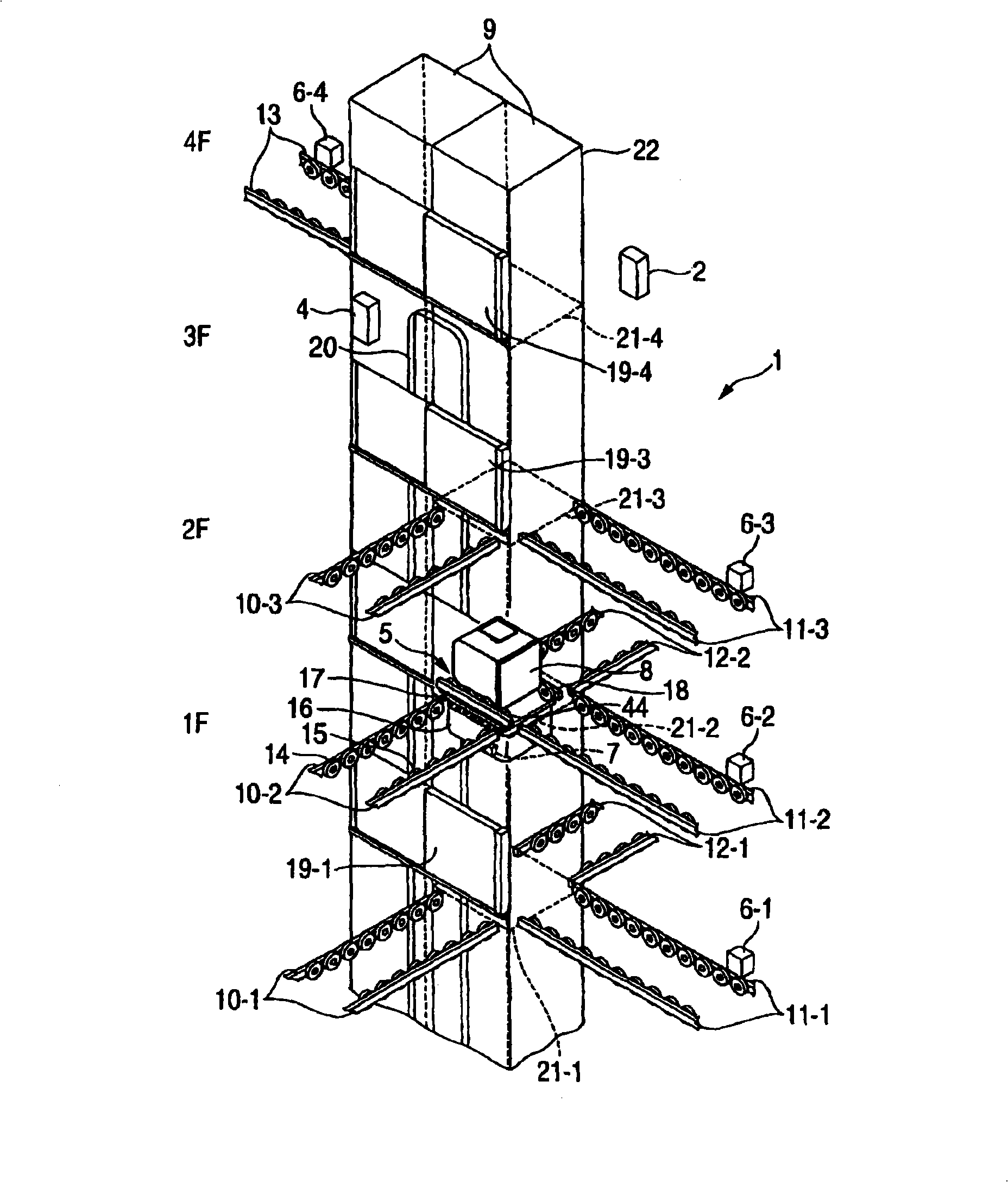
[0044] Hereinafter, an example of a specific best mode for implementing the vertical transfer device according to the present invention will be described with reference to the drawings. It should be noted that the present embodiment can be assumed to be applied to a case where a conveyor system using roller conveyors laid on multiple floors is used in a semiconductor manufacturing plant in which manufacturing processes span multiple floors.

[0045] Below, according to figure 1 The vertical transfer device according to this embodiment will be described. figure 1 It is a perspective view showing the vertical transfer device according to this embodiment.

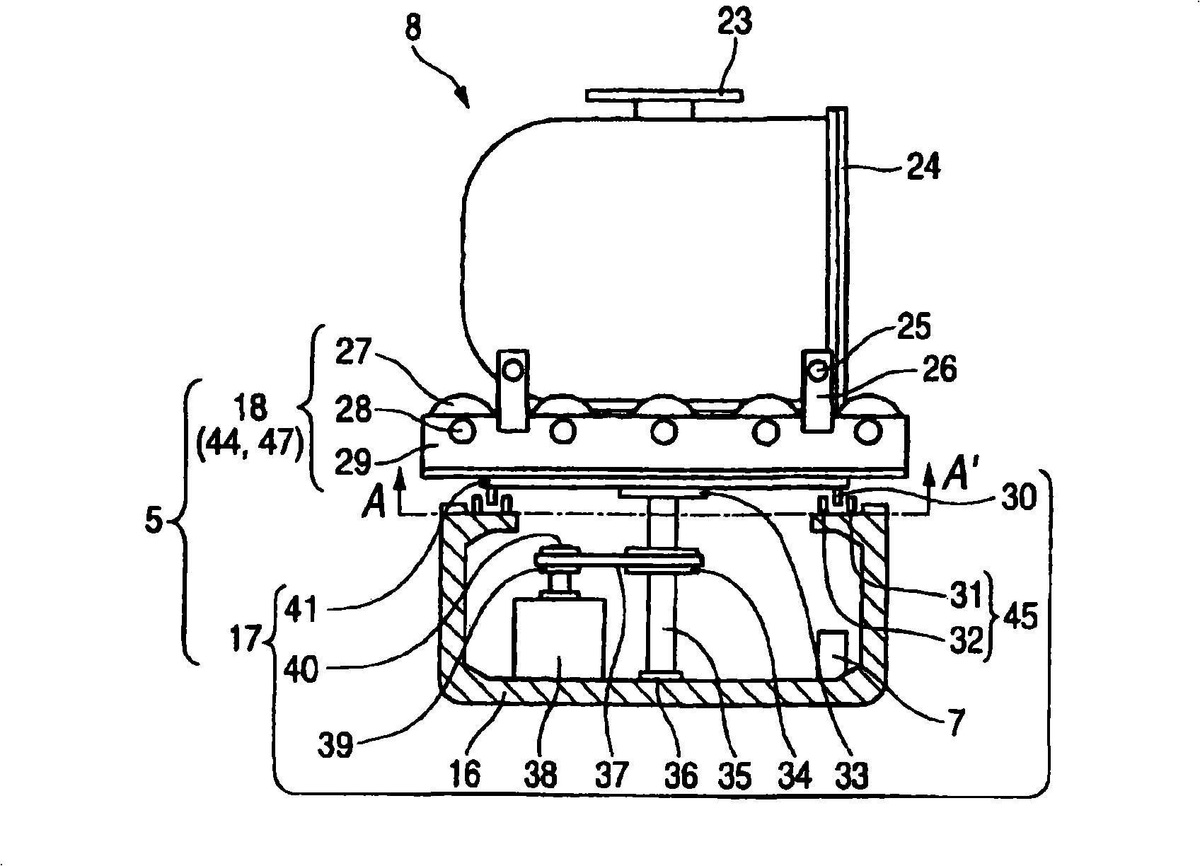
[0046] Such as figure 1 As shown, the vertical conveying device 1 has a lifting conveyor (carrying direction setting device) 5, a cable support lifting device) 20, including a lifting controller 4 and a rotary platform controller 7 ( figure 2 ) vertical transfer controller (vertical transfer control device) 3. and, figur...


PUM


Abstract

Provided is a vertical conveyance deivce. A lifting conveyor (5) is constructed from a turntable (17) and a roller conveyor (18). The roller conveyor (18) is supported on the turntable (17). A conveyor rail performs delivery or reception of a load. The turntable (17) is turned by a turntable controller (7) to align the conveyance direction of the conveyor rail with the roller conveyor (18), and after that, the conveyor rail and the roller conveyor (18) are driven to deliver or receive a FOUP (8). The lifting conveyor (5) is supported by a cable (20a) placed in a hoistway space (9) by a joint member (20b) of a cable bearer (20), and the cable bearer (20) is vertically circulated in a reciprocating manner by a lifting conveyor controller (4). In association with the movement of the cable bearer (20), the lifting conveyor (5) stops in a vertically movable manner at a port (21) placed at each floor.

Description

technical field [0001] The invention relates to a vertical conveying device which connects with multiple conveying rails laid on multiple floors and conveys conveyed articles along the vertical direction. Background technique [0002] In manufacturing plants such as semiconductor manufacturing plants and liquid crystal display panel manufacturing plants, by using conveying conveyor belts, OHT, OHS and other handling systems, according to the process flow, the devices in the manufacturing process are transported and stored (for example, in semiconductor manufacturing plants, for semiconductor substrates) substrates, glass substrates for liquid crystal display devices, glass substrates for photomasks, substrates for optical discs, etc.) In a manufacturing plant that uses a transfer system, as the scale of production expands and the manufacturing plant becomes larger, the number of manufacturing devices and the scale of the transfer system increase, and the manufacturing proces...

Claims


Application Information

Patent Timeline
Patent Type & Authority Applications(China)
IPC IPC(8): B65G47/52B65G47/53H01L21/677
CPCB65G47/54B65G47/643H01L21/67706H01L21/67715H01L21/6773H01L21/67769Y10S414/14
Inventor 大岛宗训
Owner MURATA MASCH LTD
Why Eureka
Try Eureka