Cleaner multilevel noise reduction device

A technology of vacuum cleaner and noise, which is applied in the field of vacuum cleaner manufacturing to achieve the effect of small size, excellent noise reduction effect and compact structure

Inactive Publication Date: 2008-12-31
NINGBO FUJIA IND
View PDF0 Cites 7 Cited by
  • Summary
  • Abstract
  • Description
  • Claims
  • Application Information

AI Technical Summary

Problems solved by technology

[0003] The object of the present invention is to address the defects and deficiencies of the above-mentioned prior art, and provide a multi-stage noise reduction device for vacuum cleaners with a compact structure, less internal space occupation of the vacuum cleaner, and a significant reduction in medium and low frequency noise for the vacuum cleaner manufacturing industry, so as to satisfy the vast number of users needs

Method used


Image

  • Cleaner multilevel noise reduction device
  • Cleaner multilevel noise reduction device
  • Cleaner multilevel noise reduction device

Examples


Embodiment 1

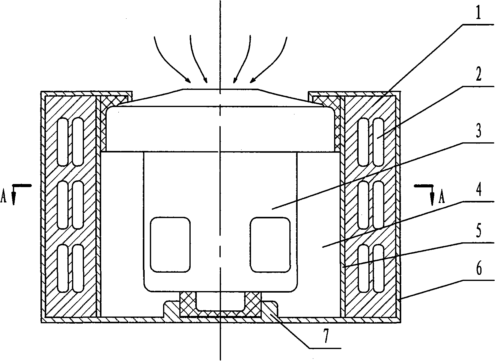
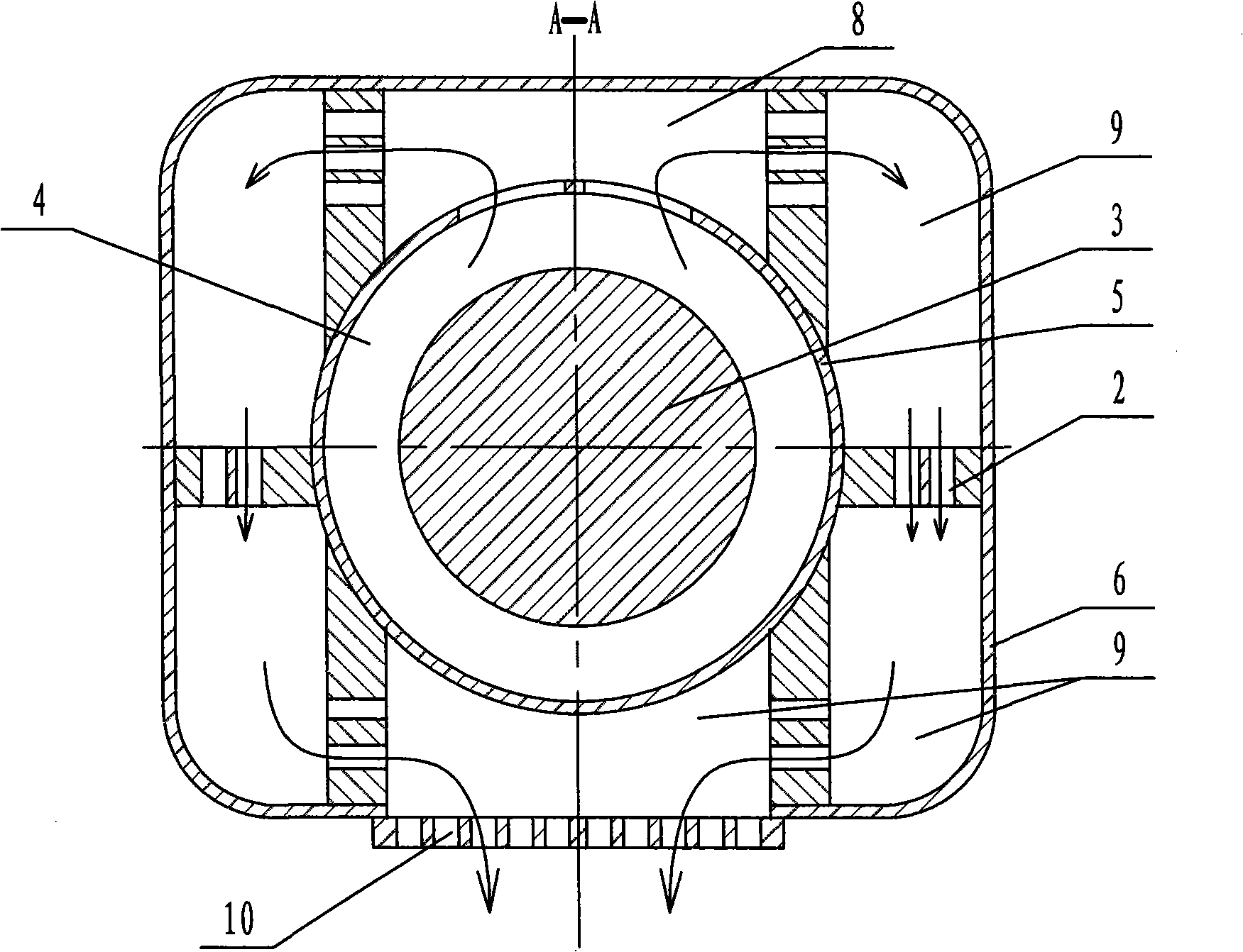
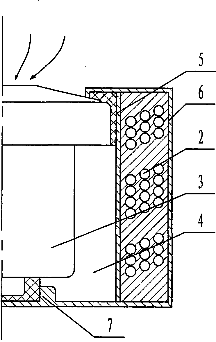
[0018] figure 1 , figure 2 , image 3 , Figure 4 It is an embodiment of the present invention.

[0019] The vacuum cleaner multi-stage noise reduction device includes an electric fan 3 and a vacuum cleaner base 7 supporting it. The motor inner cover 5 and the outer cover 6 that are spaced from each other are installed on the periphery of the electric fan, so that the inner air duct 4 and the outer air duct for air circulation are formed between the electric fan 3 and the inner motor cover 5, and the inner motor cover and the outer cover. The electric fan inner cover 5 in the figure is circular, and the outer cover 6 is rectangular or circular. One or several shrink tube brackets 1 are inserted axially in the outer air duct between the inner cover 5 and the outer cover 6 of the electric fan, which isolates the outer air duct into a resonant chamber 8 connected to the air inlet and a plurality of different lengths. The airtight expansion chamber 9. On the shrink tube sup...

Embodiment 2

[0021] Figure 5 is another embodiment of the present invention. In this embodiment, the motor inner cover 5 and the outer cover 6 arranged on the periphery of the electric fan 3 are both circular, and the shrink tube brackets 1 of the shrink tube 2 with small holes or slender holes are connected to the inside of the motor in the radial direction. Between the cover 5 and the outer cover 6, the outer air duct is radially divided into several expansion chambers 9 of different sizes or evenly distributed, and the rest of the structure is the same as that of Embodiment 1.

Embodiment 3

[0023] Image 6 It is another embodiment of the present invention. In this embodiment, the shrink tube support 1 can be sequentially connected between the motor inner cover 5 and the outer cover 6 along the axial direction of the electric fan. These small holes or slender thin holes are preferably mutually misplaced, and it divides the external air duct into a resonant chamber 8 connected to the air inlet and several expansion chambers 9 axially up and down behind the resonant chamber 8 . All the other structures are the same as in Example 1.


PUM


Abstract

The invention relates to a dust collector multi-grade noise reduction device, which comprises an electric blower fan and a dust collector base for supporting the electric blower fan, wherein, the peripheral area of the electric blower fan is provided with an inner cover and an outer cover of the electric blower fan which are arranged at intervals; a resonant chamber separated and a closed expansion chamber arranged between the inner cover and the outer cover by a shrinkage pipe bracket; the shrinkage pipe bracket is provided with a shrinkage pipeline connecting an air inlet and an air outlet. The shrinkage pipe brackets connecting the inner cover and the outer cover can be one or more than one. The shrinkage pipeline arranged on the shrinkage pipe bracket can be small holes with various shapes and with a cross section which is vertical to the shrinkage pipe bracket. The dust collector multi-grade noise reduction device has the advantages of compact structure, coaxial arrangement of the electric blower fan as well as the inner cover and the outer cover of the electric blower fan, small occupation area and small volume, which can weaken sound wave produced by the electric blower fan by a plurality of times of expansion and shrinkage of the resonant chamber, the expansion chamber and the shrinkage pipe at the transilient interface part again and again, thus having an obvious noise reduction effect.

Description

technical field [0001] The invention relates to the technical field of vacuum cleaner manufacture, in particular to a noise reduction device installed on the electric fan of the vacuum cleaner to reduce the noise of the vacuum cleaner during use. Background technique [0002] The vacuum cleaner is mainly used to suck the dust on the ground or in the crevices, and the air containing the dirt is sucked into the interior of the vacuum cleaner, separated and then discharged from the discharge port. Since the inhaled air flow generates strong vibrations in the passage provided inside the vacuum cleaner, a lot of noise is generated. At the same time, the airflow inhaled by the rotation of the high-speed electric fan will also produce strong vibrations and low-frequency noises, which make the vacuum cleaner user and all the people present feel unbearable. In order to solve this problem, people try to adopt various methods to reduce the noise of the vacuum cleaner. The most common...

Claims


Application Information

Patent Timeline
Patent Type & Authority Applications(China)
IPC IPC(8): A47L9/00
Inventor 王跃旦
Owner NINGBO FUJIA IND
Why Eureka
Try Eureka