Disposal method and equipment for exhaust gas from combustion system

A technology of waste gas treatment device and combustion device, which is applied in combustion method, combustion product treatment, gas treatment and other directions, can solve the problems of carbon dioxide recirculation, high temperature of combustion furnace, etc., and achieves reduction of driving energy, simple device structure, and simple device structure. Effect

Inactive Publication Date: 2008-12-31
ELECTRIC POWER DEVELOPMENT COMPANY +1
View PDF1 Cites 22 Cited by
  • Summary
  • Abstract
  • Description
  • Claims
  • Application Information

AI Technical Summary

Problems solved by technology

[0010] However, even with the technology shown in Patent Document 1, when the oxygen combustion is performed at the start-up stage of the burner, the carbon dioxide cannot be recirculated, so there is a problem that the burner generates high temperature, so the air burner is carried out at the initial stage of the start-up of the burner.

Method used


Image

  • Disposal method and equipment for exhaust gas from combustion system
  • Disposal method and equipment for exhaust gas from combustion system

Examples


Embodiment Construction

[0057] Hereinafter, embodiments of the present invention will be described with reference to the drawings.

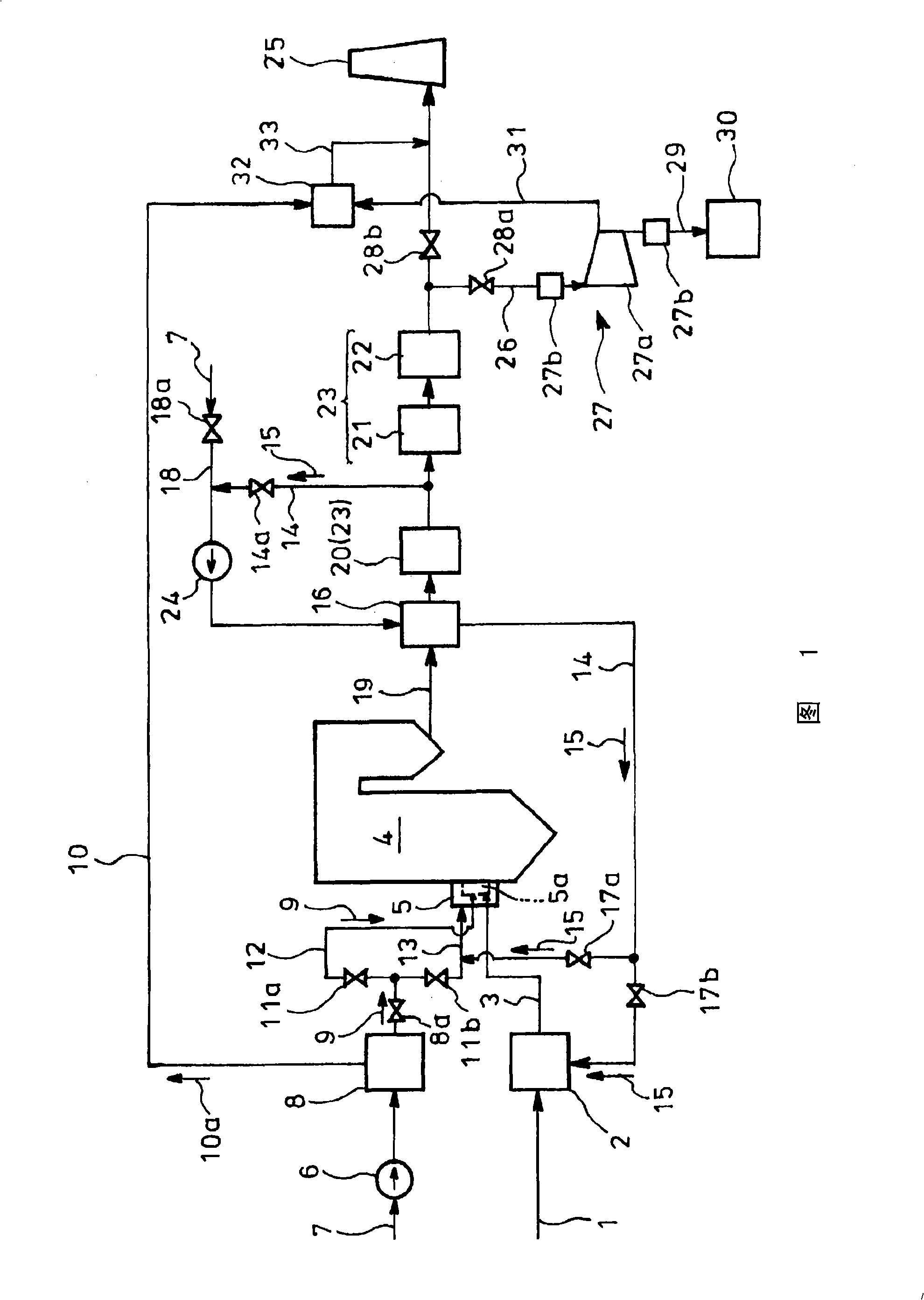
[0058] Fig. 1 is a schematic flow diagram showing an example of an apparatus for implementing the present invention, in which coal 1 as fuel is pulverized by a mill 2 used as a fuel supply means to form pulverized coal 3, and is supplied in a wind box 5 of a combustion furnace 4 (boiler) Has burner 5a. The air 7 from the blower 6 is supplied to the oxygen separation device 8 and separated into oxygen 9 and other nitrogen-based gas 10a, and the generated oxygen 9 passes through the regulator 8a, and then is shunted to the direct flow through the oxygen flow regulator 11a, 11b. A part of the oxygen 9 is directly supplied to the burner 5 a through the direct supply line system 12 and the mixed supply line system 13 . On the other hand, the remainder of the oxygen 9 is mixed with a part of the recirculation gas 15 preheated in the air preheater 16 described later and guide...


PUM


Abstract

The invention aims at separating carbon dioxide from exhaust combustion gas effectively and making it possible to discharge the residual exhaust combustion gas enriched in the exhaust gas components other than carbon dioxide by the separation of carbon dioxide into the atmosphere. Air (7) is separated into oxygen (9) and a nitrogen-base gas (10a) in an oxygen separator (8); coal (1) is burnt with the oxygen (9) in a burner (5a) in a combustion furnace (4); an exhaust combustion gas from the furnace (4) is subjected to exhaust gas treatment; a part of the resulting exhaust combustion gas is recycled to the burner (5a), while the remainder is compressed: the carbon dioxide (29) liquefied by the compression is taken out, while the residual exhaust gas component (31) which is not liquefied by compression is mixed and diluted with the nitrogen-base gas (10a) obtained by separating the oxygen (9) from the air (7) in the oxygen separator (8); and the diluted exhaust gas is discharged into the atmosphere.

Description

technical field [0001] The present invention relates to a method and device for treating exhaust gas of a combustion device, and in particular to a combustion control method capable of effectively separating carbon dioxide in combustion exhaust gas and discharging combustion exhaust gas containing other exhaust gas components concentrated by the separation of carbon dioxide into the atmosphere and device. Background technique [0002] In recent years, global warming has been widely raised as an environmental problem on a global scale. A major cause of known global warming is due to atmospheric carbon dioxide CO 2 Concentrations have increased, and thermal power plants have drawn attention as a stationary source of emissions of these substances. Petroleum, natural gas, and coal are used as fuel for thermal power generation. Coal, in particular, has a large amount of reserves that can be mined, and the demand is expected to increase in the future. [0003] Compared with nat...

Claims


Application Information

Patent Timeline
Patent Type & Authority Applications(China)
IPC IPC(8): F23J15/00F23C99/00B01D53/62F23L7/00F23C9/08F25J3/00
CPCB01D53/62B01D2257/504F23C9/00F23D1/00F23G2900/00001F23J15/006F23J15/02F23J15/06F23J2215/50F23J2900/15061F23L7/007F25J3/04533F25J3/04563F25J2245/42F25J2260/42F25J2260/80F23L2900/07001Y02P20/129C01B32/50Y02C20/40Y02E20/32Y02E20/34Y02P20/151F23J15/00F23C99/00F23L7/00
Inventor 大川正文藤森俊郎高野伸一山田敏彦
Owner ELECTRIC POWER DEVELOPMENT COMPANY
Why Eureka
Try Eureka