Vertical type internal broaching machine

An internal broaching machine and vertical technology, applied in the field of broaching machines, can solve the problems of high manufacturing cost, large power consumption, and large energy consumption, and achieve the effect of solving high production cost, improving production efficiency, and reducing production cost

Inactive Publication Date: 2009-01-07
庄全林
View PDF0 Cites 12 Cited by
  • Summary
  • Abstract
  • Description
  • Claims
  • Application Information

AI Technical Summary

Problems solved by technology

[0003] 1. Large resource consumption: the existing technology adopts the upper and lower frames of the cast steel main body, which is large in size and complicated in process, etc.
[0004] 2. Large energy consumption: full hydraulic transmission, large power consumption, complex structure
[0005] 3. The speed of lifting the tool is slow, and the fixture is not universal: the speed of any broaching machine is the same during the broaching process, and it cannot be fast
Existing defects lie in the slow speed of hydraulic knife transfer, complex structure, complicated and time-consuming replacement of broaches
There are many kinds of clamping on the tail of the existing broaches, such as spring steel ball clamping type, pin type, etc. The defect is that different clamps need to be replaced to replace different broaches. For example, the size of the broach is not much different. If the size of the broaches differs too much, the fixture must be replaced
[0006] 4. Broach head fixture: The existing broach head clamping adopts phase block type automatic clamping without power. The defect is that iron filings are always accumulated around the broach during the broaching process. When the chuck is withdrawn, the surrounding iron filings fall into the inner cavity of the chuck, and the chuck is often stuck, and the size of different broaches is too different, so it is necessary to replace different chucks. It is very troublesome to replace the chuck. Generally, the manufacturer only allocates one or two sets of chucks to the user. , if users add other new products, they need to make or customize, and the cost is quite high
Both the broach and the fixture have machining tolerances, and the chuck will be worn after long-term use, and the center of the broach will be offset, not on the vertical line, affecting product quality
[0008] Therefore, the existing full-hydraulic vertical internal broaching machine has complex structure, low work efficiency, large energy consumption, high manufacturing cost and high price, which are generally unaffordable for small and medium-sized enterprises.

Method used


Image

  • Vertical type internal broaching machine
  • Vertical type internal broaching machine
  • Vertical type internal broaching machine

Examples


Embodiment Construction

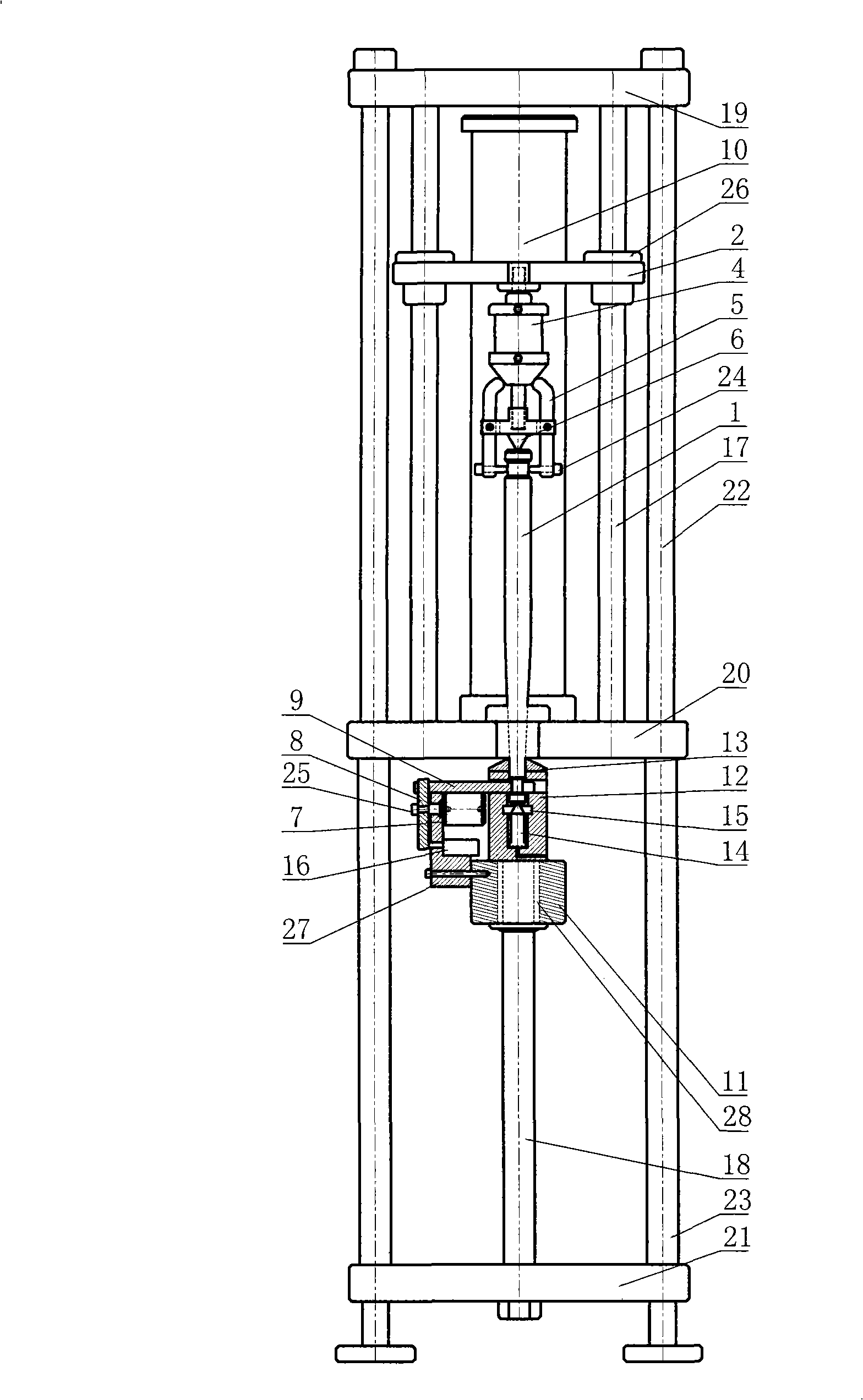
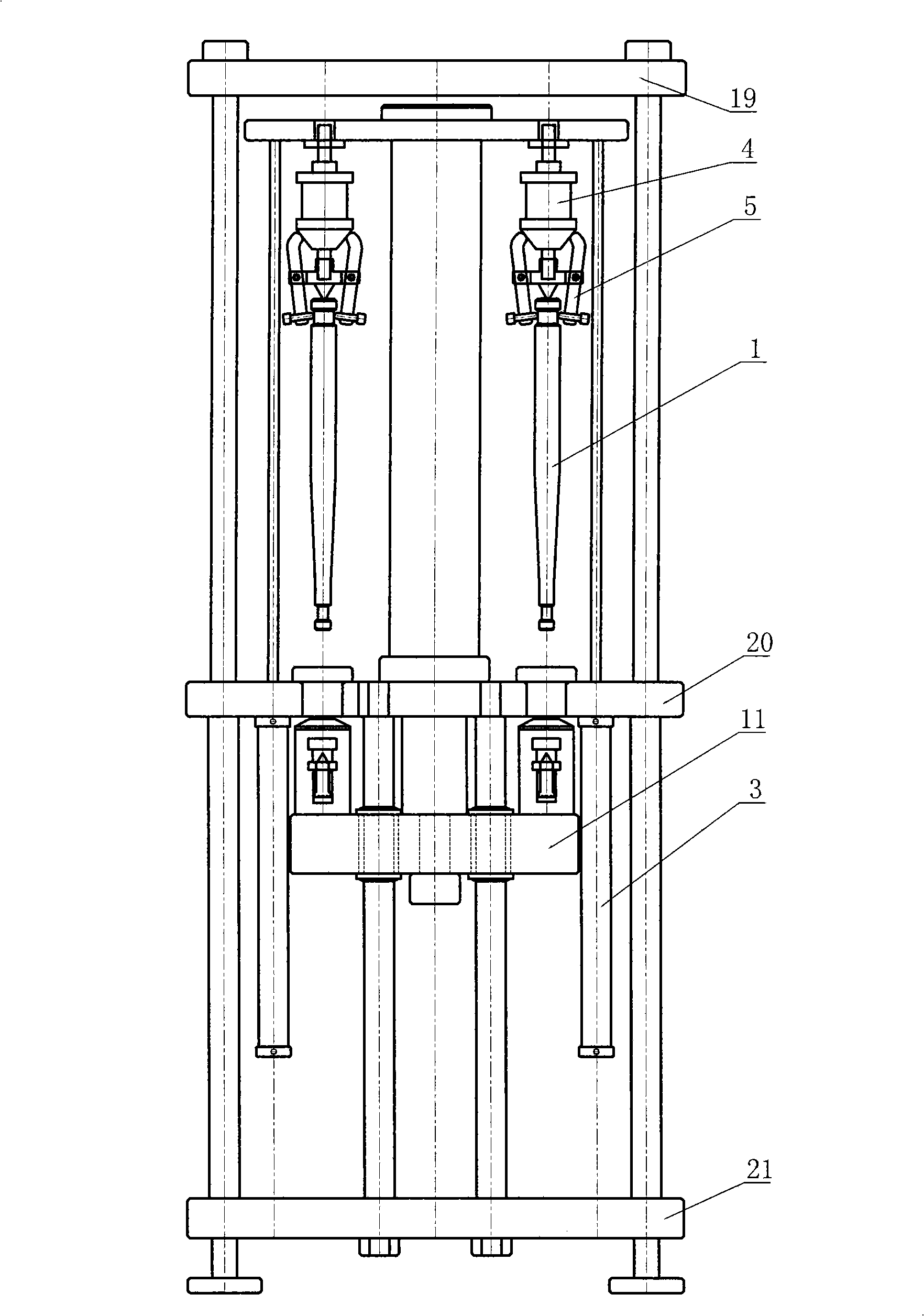
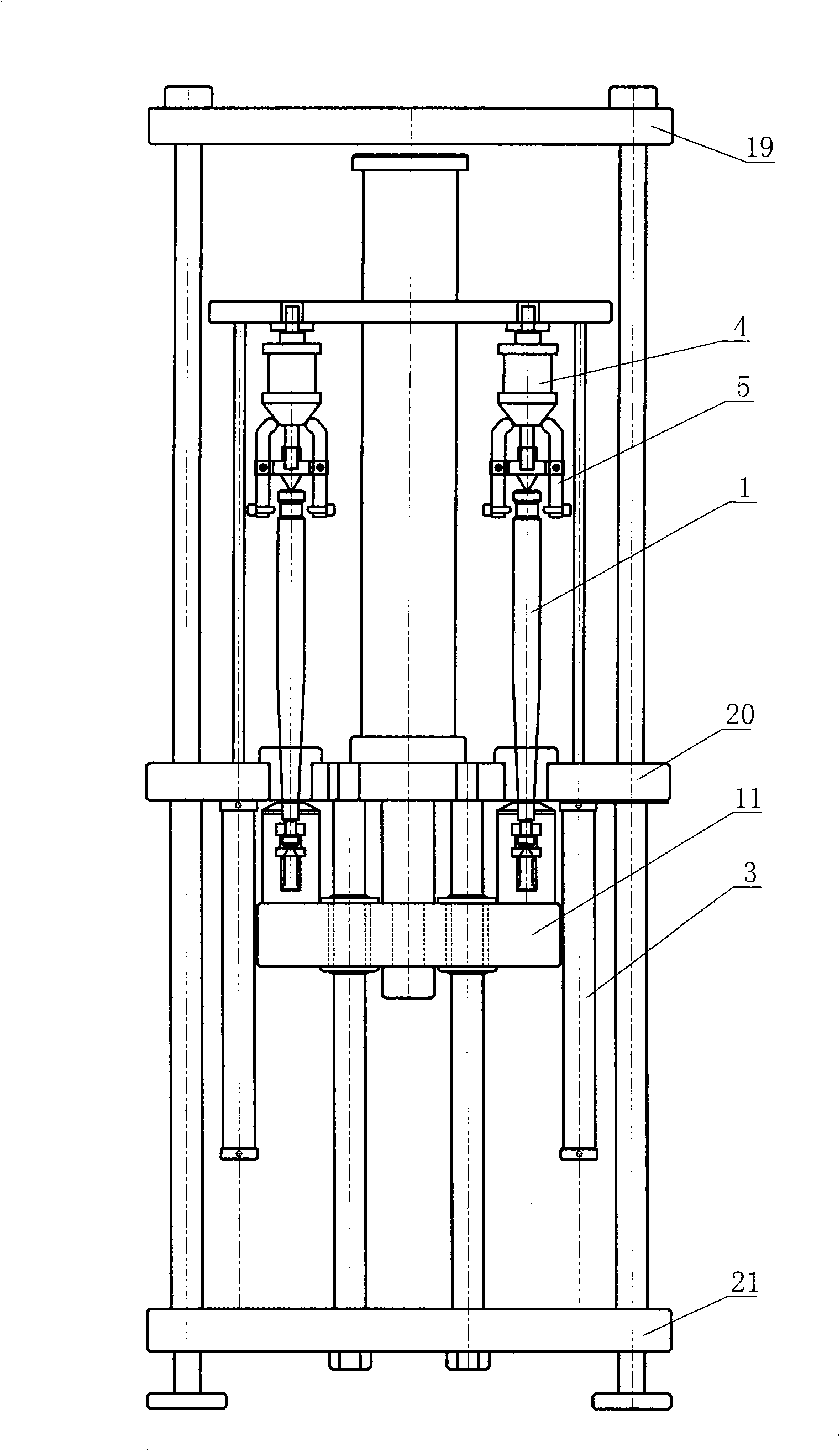
[0025] like figure 1 , 2 As shown, the vertical internal broaching machine includes a vertical frame, a broach 1, and a main hydraulic transmission assembly. The main hydraulic transmission assembly is installed on the vertical frame, and also includes a pneumatic clamping mechanism, a lifting knife movable plate 2, Knife cylinder 3, guide post 17 of the movable plate for lifting the knife, and a pneumatic clamping mechanism. The pneumatic clamping mechanism can clamp the tail of the broach 1. The pneumatic clamping mechanism can clamp the head of the broach 1. The pneumatic clamping mechanism It is fixed on the movable plate for lifting the knife 2, the movable plate for lifting the knife 2 is arranged on the guide column 17 of the movable plate for lifting the knife, the cylinder 3 for lifting the knife is connected with the guide column 17 of the movable plate for lifting the knife, and can control the guide column 17 of the movable plate for lifting the knife to move up an...


PUM


Abstract

The invention discloses a vertical internal broaching machine, which comprises a vertical frame, a broaching tool and a main fluid drive component, wherein the main fluid drive component is mounted on the vertical frame. The vertical internal broaching machine further comprises a pneumatic clamping mechanism, a griffe movable plate, a griffe cylinder, a guide pole of the griffe movable plate, and a pneumatic flashboard mechanism. The pneumatic clamping mechanism can clamp the tail part of the broaching tool; the pneumatic flashboard mechanism can clamp the head part of the broaching tool; the pneumatic clamping mechanism is fixed on the griffe movable plate; the griffe movable plate is arranged on the guide pole of the griffe movable plate; the griffe cylinder is connected with the guide pole of the griffe movable plate, and can control the guide pole of the griffe movable plate to move upwards and downwards; and the pneumatic flashboard mechanism is fixed on the main fluid drive component. The vertical internal broaching machine adopts pneumatic power to perform assistant actions, enables rapid clamping and back stroke, optimizes the product structure, increases the production efficiency, reduces the manufacture cost, and lowers the consumption of production energy.

Description

【Technical field】 [0001] The invention relates to a broaching machine, in particular to a vertical internal broaching machine for broaching through holes with various geometric shapes. 【Background technique】 [0002] The current vertical internal broaching machines all adopt cast iron frame and full hydraulic transmission. There are many defects in the vertical inner broaching machine of this structure: [0003] 1. Large resource consumption: the existing technology adopts the upper and lower frames of the cast steel main body, which is large in size and complicated in process. [0004] 2. Large energy consumption: full hydraulic transmission, large power consumption and complex structure. [0005] 3. The speed of lifting the tool is slow, and the fixture is not universal: the speed of any broaching machine is the same during the broaching process, and it cannot be fast. There is a certain period of time for the main oil cylinder to return and retract. Existing defects l...

Claims


Application Information

Patent Timeline
Patent Type & Authority Applications(China)
IPC IPC(8): B23D41/00B23D41/04B23D41/08B23D41/02B23Q3/00
Inventor 庄全林
Owner 庄全林
Why Eureka
Try Eureka