Automatic stamping machine and programmed control method

An automatic stamping machine and stamping technology, which is applied in printing, stamping, etc., can solve the problems of undisclosed and optimized structure, optimized performance, etc., and achieve the effects of avoiding motor damage accidents, standard stamping, and preventing motor damage

Inactive Publication Date: 2009-01-07
四川道亨计算机软件有限责任公司
View PDF1 Cites 31 Cited by
  • Summary
  • Abstract
  • Description
  • Claims
  • Application Information

AI Technical Summary

Problems solved by technology

However, this structure does not use program control, nor does it disclose and propose its optimized structure and corresponding optimized p

Method used


Image

  • Automatic stamping machine and programmed control method
  • Automatic stamping machine and programmed control method
  • Automatic stamping machine and programmed control method

Examples


Embodiment 1

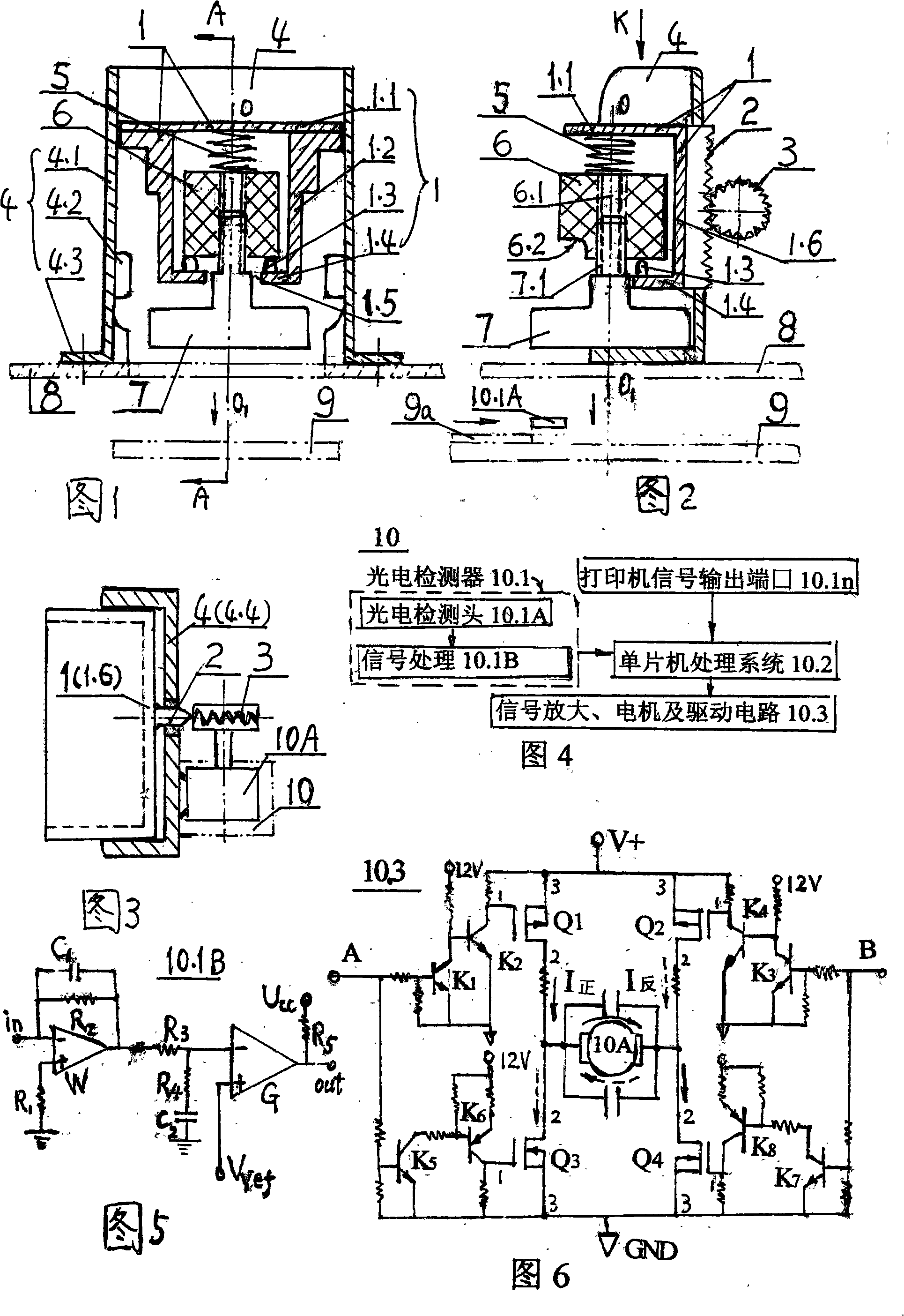
[0023] Embodiment 1: see Fig. 1~ Figure 7 , Figure 9 .

[0024] As shown in Figures 1 to 2, the transmission bracket 1 is provided with a top plate 1.1, a lower plate 1.4 and two side plates 1.2 connecting them, and a rear plate 1.6 may also be provided. Place stage clip 5, seal handle 6 and seal 7 successively under top plate 1.1, seal is connected with seal handle threaded hole 6.1 by threaded rod 7.1 on the upper end, the two are connected as a whole. The card 1.3 is fixed on the bottom plate 1.4 of the transmission bracket, and the stamping handle 6 is clamped between the upper plane clip spring and the lower plane card 1.4. See Fig. 1, lower plate 1.4 has breach 1.5, so that when stamping handle 6 is taken off and adds stamp oil, stamp can be taken out simultaneously. As shown in Figure 2, there is a gap 6.2 below the outer height of the stamping handle, which is convenient for taking out the stamping handle by hand, and the threaded hole 6.1 of the stamping handle is...

Embodiment 2

[0030] Embodiment 2: see Fig. 1~Fig. 4, Fig. 6~ Figure 8

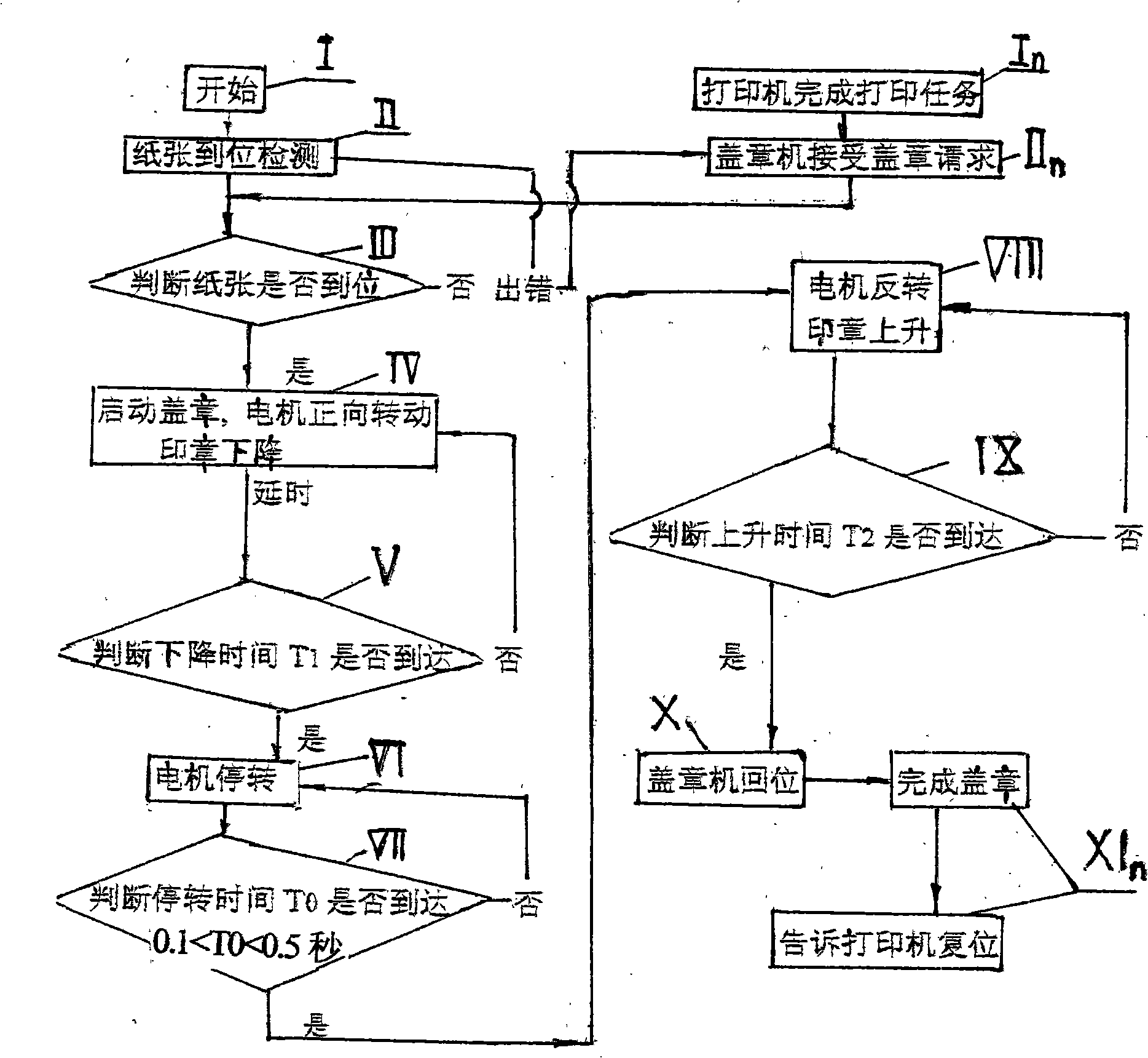
[0031] The automatic stamping machine in Embodiment 2 is used in conjunction with the printing, paper separating and paper feeding systems of the automatic payment and billing terminal. Except that the automatic control device 10 and the program control method are slightly changed, all the others are identical to Embodiment 1. The 'upper program device' described in the above program in Embodiment 2 is a 'printer'. The differences are as follows: (i). See Fig. 4, the automatic control device 10 is composed of a printer signal output port 10.1n, a single-chip microcomputer processing system 10.2, a signal amplifier, a motor and a driving circuit 10.3. The photodetector 10.1 in Embodiment 1 is replaced by a printer signal output port 10.1n. ii. see Figure 7 , complete the printing task with step In. printer respectively; IIn stamp machine accepts stamp request; Alternative embodiment 1 step I starts and II paper in ...


PUM


Abstract

The invention relates to an automatic sealing machine and a program-controlled method. A transmission bracket driven through a gear rack and a motor is installed in an overall bracket, and a compression spring, a sealing handle and a stamp connected through a thread through-hole are installed in the transmission bracket. The sealing handle is pressed between the compression spring and a transmission bracket bottom board. The automatic sealing saves the manual trouble, is time-saving and labor-saving. The arrangement of the compression spring ensures that the descending process of the stamp becomes the optimal sealing process, avoids the damage to the motor, and provides a transient time from the stamp pressing to the stamp lifting. After the sealing handle is taken out, the stamp oil is very convenient to be refilled from the through-hole. A single-chip microcomputer is arranged and controlled through a program; a DC motor two-way drive circuit including a field effect pipe, the loss is low, the directional change is quick and the control is convenient. A photoelectric detector can be used for detecting whether the paper is in place, then the motor is controlled to rotate in the forward direction, the stamp descends; the motor is stopped; when the motor rotates in the reverse direction, the stamp ascends; the run-down time is controlled through the program, thereby the sealing is standard, and the effect is good. The automatic sealing machine can be separately used, and can also be matched with any program control system requiring automatic sealing, such as the printing, the separating and the feeding systems of an automatic paying and invoicing terminal.

Description

(1) Technical field: [0001] The invention relates to an automatic stamping machine and a program control method. The stamping machine can be used independently or in combination with other program-controlled systems that require automatic stamping. For example: It is used in conjunction with the printing, paper separation and paper feeding system of the automatic payment and billing terminal. It belongs to stamping machine (B41K). (two) background technology: [0002] At present, the stamping behavior is all manual work, including ink pad stamps and steel seals, etc. are all achieved by manual stamping. The former can be realized by directly holding the stamp and pressing it down, and the latter can be achieved with a simple steel stamper. Although manual stamping can generally meet the demand, with the development of the economy, the workload of stamping in many industries is increasing, such as taxation departments, water, electricity, gas fee collection departments, etc....

Claims


Application Information

Patent Timeline
IPC IPC(8): B41K3/02B41K3/62
Inventor 何力
Owner 四川道亨计算机软件有限责任公司
Why Eureka
Try Eureka