Coal gas waste gas, waste slag and waste ash comprehensive utilization process and apparatus

A coal-to-gas and waste residue technology, which is used in the manufacture of combustible gas, sustainable manufacturing/processing, and the petroleum industry. The effect of saving energy and improving efficiency

Inactive Publication Date: 2009-01-21
邓立玮
View PDF0 Cites 6 Cited by
  • Summary
  • Abstract
  • Description
  • Claims
  • Application Information

AI Technical Summary

Problems solved by technology

[0005] In this process, the recovery of blowing air mainly uses the high-temperature flue gas generated after the combustion of synthetic relaxation gas to ignite the blowing air for gas generation. In order to enhance heat storage, a large number of checker bricks are placed in the combustion furnace, resulting in large system resistance and low efficiency of gas generation and blowing. reduce
In addition, due to the constant amount of synthe

Method used


Image

  • Coal gas waste gas, waste slag and waste ash comprehensive utilization process and apparatus
  • Coal gas waste gas, waste slag and waste ash comprehensive utilization process and apparatus
  • Coal gas waste gas, waste slag and waste ash comprehensive utilization process and apparatus

Examples


Embodiment 1

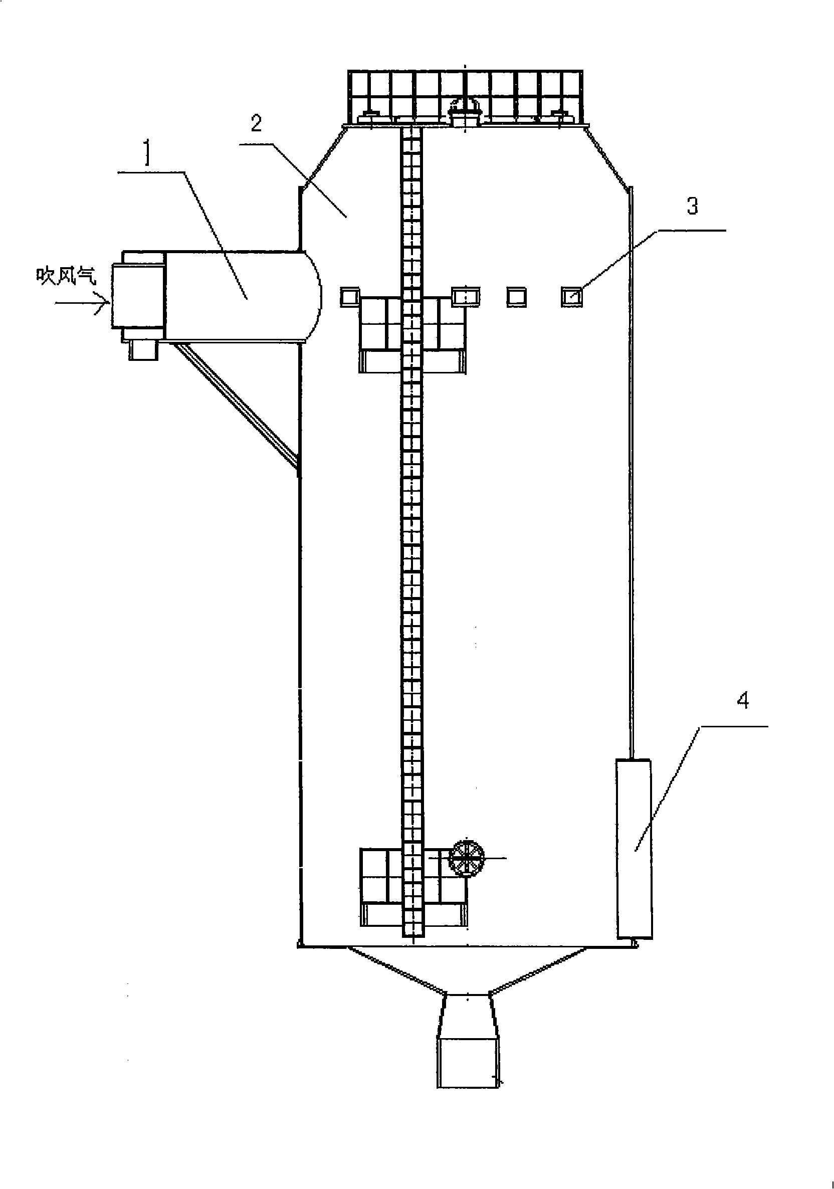
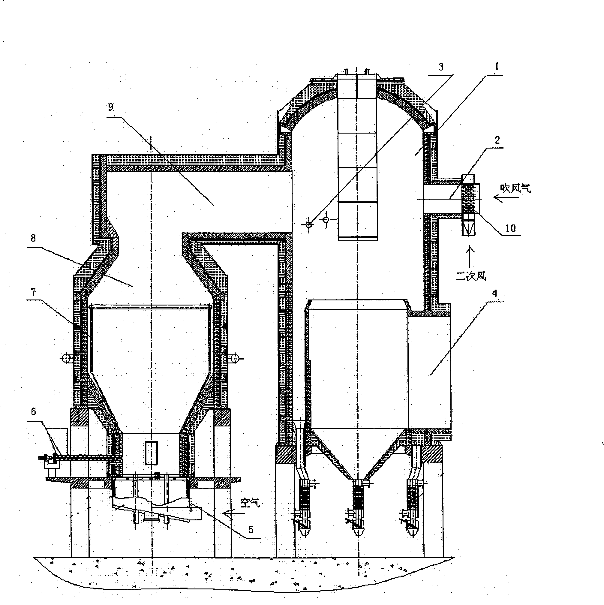
[0030] Embodiment one: see figure 2 As shown in Figure 3, the comprehensive utilization process of waste gas, waste residue and ash from coal gasification is to combine fluidized bed furnace 8 with coal gas blowing waste heat recovery system, and fluidized bed furnace 8 uses the waste residue and waste ash after coal gasification as fuel for secondary combustion , generate high-temperature flue gas to ignite the blowing gas in the blowing gas burner 1, and the flue gas after the burning of the blowing gas passes through the waste heat recovery system and is discharged into the atmosphere by the chimney.

[0031] The specific process steps are as follows:

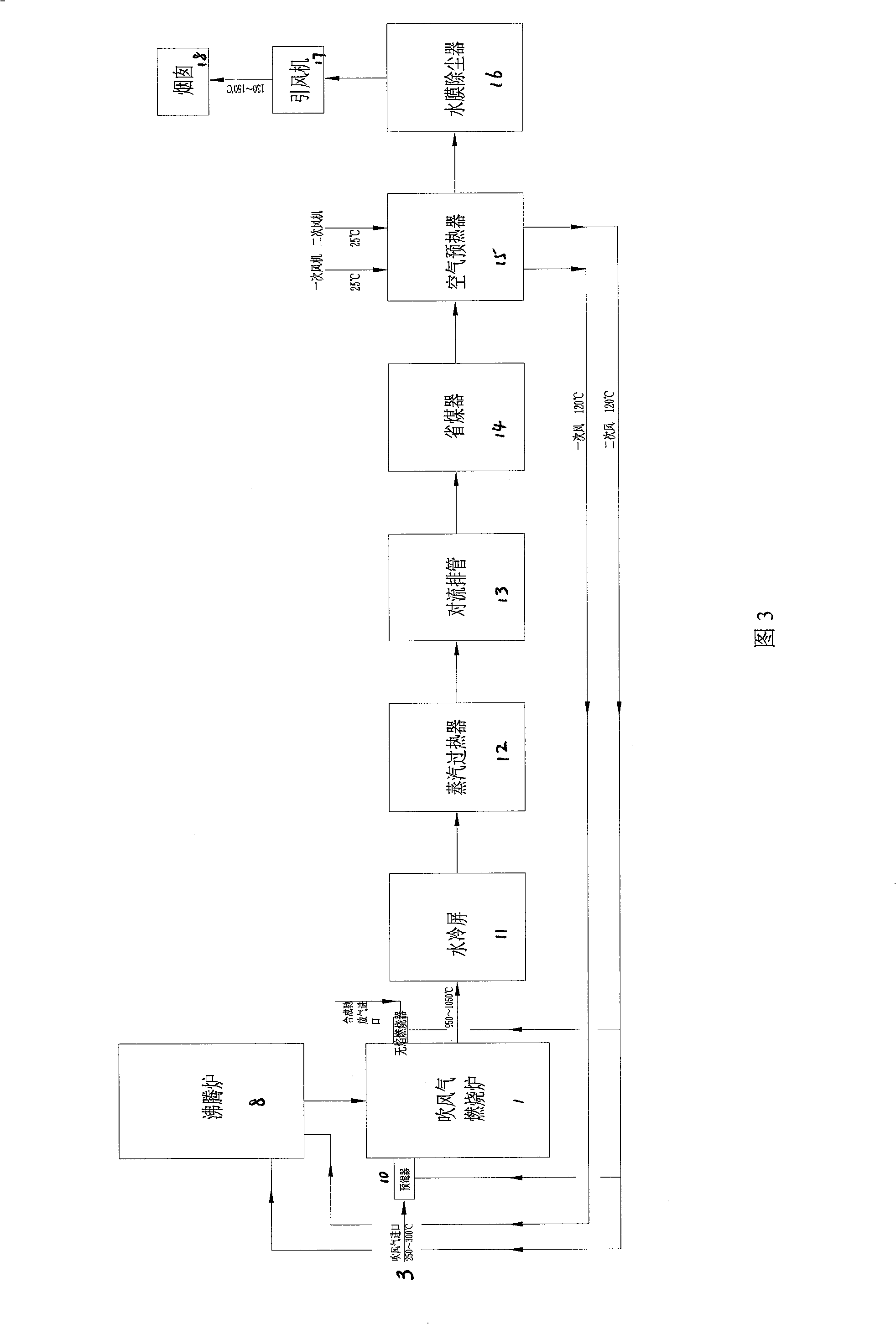
[0032] a. The gas-making slag and coal ash are sent to the lower part of the fluidized fluidized furnace 8 by the spiral coal feeder 6, and the primary air preheated to 120±15°C by the air preheater 15 is used for combustion reaction;

[0033] b. The high-temperature flue gas produced by the fluidized fluidized furnace 8 e...

Embodiment 2

[0037] Embodiment two: see figure 2 As shown in Fig. 4, the waste gas, waste residue and ash comprehensive utilization device of this coal-to-gas system is connected to the water cooling screen 11, the steam superheater 12, the convection exhaust pipe 13 of the waste heat boiler, and the economizer in sequence from the flue gas outlet 4 of the blowing gas combustion furnace 1 14. After the air preheater 15 and the water film deduster 16, it passes through the induced draft fan 17, and finally connects to the chimney 18 to form a blowing air waste heat recovery system, which is characterized in that there is a fluidized fluidized furnace 8 and the blowing air combustion furnace 1 connection, the high-temperature flue gas outlet of the fluidized fluidized furnace 8 communicates with the furnace upper chamber of the blowing gas combustion furnace.

[0038] The above-mentioned fluidized fluidized furnace 8 is combined with the blowing gas combustion furnace to form a composite mi...


PUM


Abstract

The invention relates to a process for comprehensively utilizing waste gas, waste slag and waste ash of coal-making gas and a device thereof. The process combines a boiling furnace and a blowing gas residual heat reclaiming system of coal-making gas together; the boiling furnace utilizes the waste slag and waste ash after coal-making gas as fuel for secondary combustion; high-temperature flue gas is produced to ignite the blowing gas in a blowing gas combustion furnace; and flue gas produced after the blowing gas is combusted passes through the residual heat reclaiming system and is exhausted to atmosphere by a chimney. The device is combined into a whole by the boiling furnace and the blowing gas combustion furnace of the blowing gas residual heat reclaiming system of the coal-making gas.

Description

technical field [0001] The invention relates to a process and device for recovering and utilizing waste heat of blowing gas from coal-to-gas, in particular to a process and a device to comprehensively utilize waste gas, waste residue and ash from coal-to-gas. Background technique [0002] At present, there are two main ways to recover the blown gas from coal gas production: one is to recover the waste heat of the blown gas from gas production, and its combustion form is the up-combustion regenerative type. Blowing air, heat recovery, by-product steam, and environmental protection, this method requires a large amount of synthesis gas. Another kind of gas-making blowing gas waste heat boiler recovery, on the basis of the first generation, the combustion nozzle is added, the checker bricks in the furnace are reduced, the resistance in the furnace is greatly reduced, and the blowing stage of the gas-making furnace is reduced. The resistance increases the load of the gas-making ...

Claims


Application Information

Patent Timeline
IPC IPC(8): C10J3/86
CPCY02P20/10Y02P20/129
Inventor 邓立玮
Owner 邓立玮
Why Eureka
Try Eureka