Energy-saving type low voltage set aluminum cell

An aluminum electrolytic cell and low-voltage technology, which is applied in the field of energy-saving low-voltage setting aluminum electrolytic cell, can solve the problems of staying in the theoretical discussion and laboratory test stage, the cell voltage setting is too high, and the output of electrolytic aluminum decreases. Achieve the effects of stable electrolysis process operation, reduced production power consumption, and balanced technical parameters

Inactive Publication Date: 2009-01-21
高德金 +1
View PDF0 Cites 12 Cited by
  • Summary
  • Abstract
  • Description
  • Claims
  • Application Information

AI Technical Summary

Problems solved by technology

[0007] Generally, for every increase in the pole distance of 10mm thickness, the process voltage drop of the electrolytic cell will increase by about 350mV, resulting in an extra power consumption of about 1000kwh per ton of aluminum.
At the same time, the aluminum liquid produced during the electrolysis process can produce secondary oxidation reactions under the working conditions in the tank, resulting in a decrease in the output of electrolytic aluminum and an increase in loss
[0008] In order to eliminate the defects in the electrolytic cell structure and process design caused by the current aluminum electrolytic cell, which is caused by the existing intermittent time-point aluminum suction process, reduce power consumption, and increase the production capacity of electrolytic aluminum, the electrolytic aluminum industry at home and abroad It is proposed to change the bottom surface of the molten pool of the electrolytic cell, which is the upper surface of the inner lining of the cathode carbon block, from a horizontal design to an inclined design with a certain slope, or to set up an aluminum liquid diversion groove on the upper surface of the inner lining of the horizontal cathode carbon block. The design scheme intends to discharge the aluminum liquid generated in the electrolytic cell immediately and continuously, and adopts the design scheme of reducing the aluminum liquid layer, reducing the pole distance voltage, and reducing the power consumption of the electrolytic aluminum production process, but due to the production cost The design of the electrolytic cell structure for the instant discharge of aluminum liquid, the electrolytic operation process, the electrolytic cell control method and many other technical problems are difficult to solve. They have been stuck in the stage of theoretical discussion and laboratory testing, and have never been implemented.
[0009] In order to solve the problem of the high pole distance setting of the current general aluminum electrolytic cell, the voltage setting of the cell is too high, and in order to solve the design problem of the cell structure of the existing technology that the aluminum liquid produced by the electrolytic cell can be discharged immediately under the electrolytic working conditions, To solve various technical problems such as electrolytic operation process and electrolytic cell control method, to realize the low pole distance and low voltage setting of electrolytic aluminum, and to reduce the power consumption of electrolytic aluminum production, we have specially developed an energy-saving low voltage setting Design scheme of aluminum electrolytic cell

Method used


Image

  • Energy-saving type low voltage set aluminum cell
  • Energy-saving type low voltage set aluminum cell
  • Energy-saving type low voltage set aluminum cell

Examples


Embodiment Construction

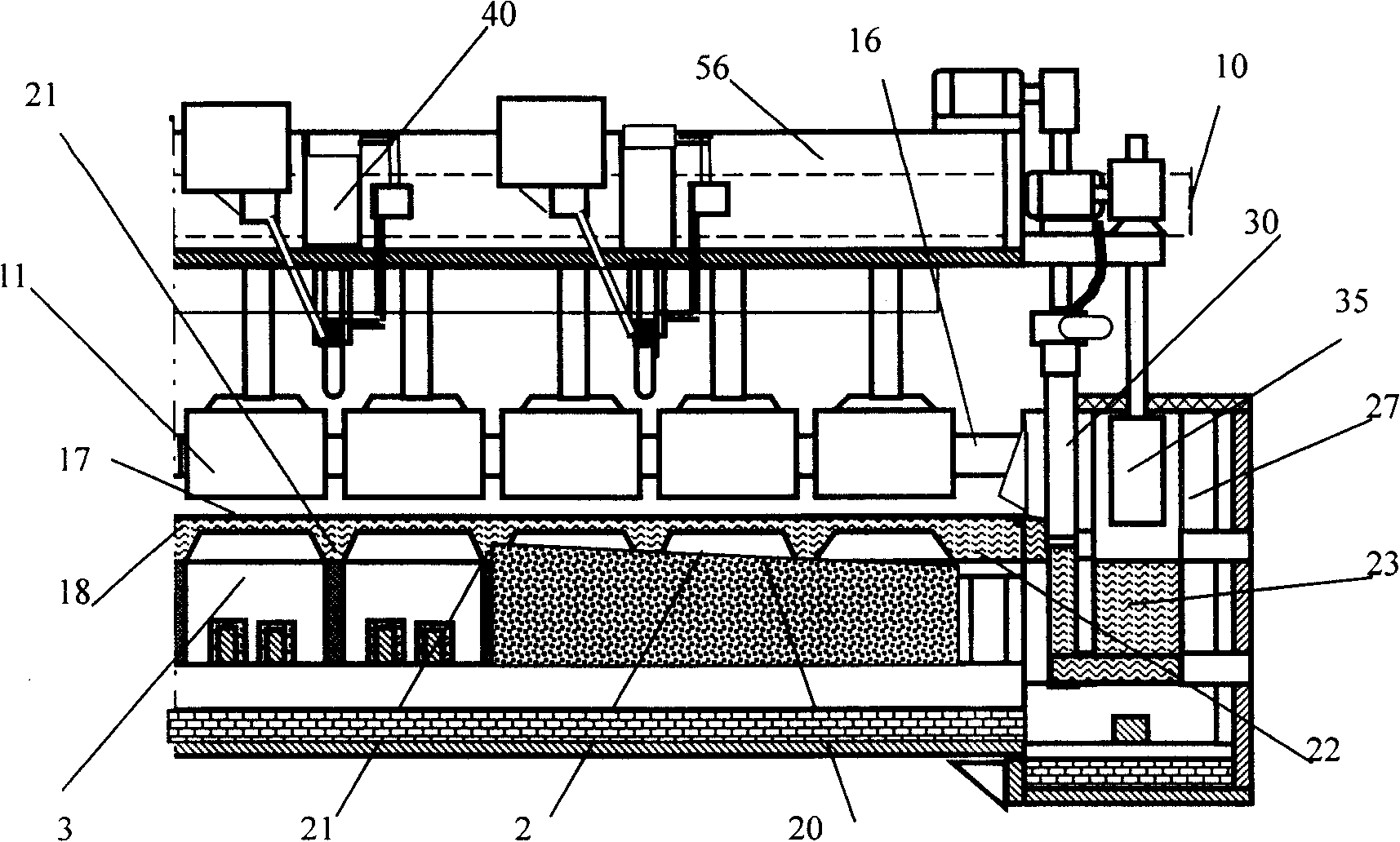
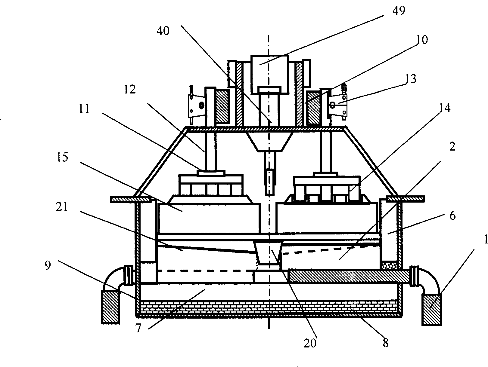
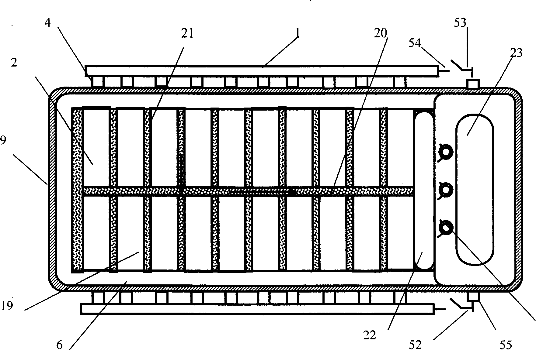
[0035] Such as figure 1 , figure 2 , image 3 As shown in , the energy-saving low-voltage electrolytic cathode lining is built. In the steel shell 9, a cathode lining 2 is constructed on the insulation layer 8 and the anti-leakage material layer 7. The cathode lining 2 is made of cathode carbon Block 3, cathode steel rod 4, tamping paste 5, side carbon 6 are built by masonry, the upper surface of the cathode lining 2 is rammed with a layer of graphite carbon titanium boride coating 19, and the cathode lining 2 is close to the aluminum end side The end portion is configured with an aluminum storage tank 27, and a diversion coagulation tank 22 is configured between the end of the cathode lining 2 side and the aluminum storage tank 27.

[0036] Such as image 3 , Figure 4 , Figure 5 , Figure 6 As shown, the main liquid aluminum diversion groove 20 and the aluminum liquid branch diversion groove 21 are constructed at the position of the upper part of the cathode liner 2 ...


PUM

PropertyMeasurementUnit
power consumptionaaaaaaaaaa

Abstract

An energy-conservation low-voltage set aluminum electrolytic bath has a structure that a bath structure is provided with a cut-off device which can adjust the height of an interface of an aluminum liquid layer generated inside the electrolytic bath and can control the flow rate of the aluminum liquid, as well as an aluminum liquid storing tank which can carry out electrode heating for an aluminum liquid inside an aluminum containing tank and ensure that the generated aluminum liquid inside the electrolytic bath flows into the aluminum containing tank through a diversion hole under the control of the aluminum liquid cut-off device. The energy-conservation low-voltage set aluminum electrolytic bath solves the problems that the prior commonly used electrolytic bath can not realize continuous timely discharge and manual adjustment and control of the generated aluminum liquid; meanwhile, a feasible design proposal for the energy-conservation low-voltage set aluminum electrolytic bath is provided in order to realize timely discharge of the generated aluminum liquid inside the electrolytic bath under the condition of an electrolytic operating mode, to eliminate the negative influence on electrolyte height, namely high polar distance and high voltage set caused by a magnetic field and a magnetic rotational flow generated by an aluminum liquid layer, and to reduce the electricity consumption during manufacturing electrolytic aluminum under the condition that the electrolytic bath is in an operating mode of low polar distance and low voltage; moreover, the design proposal for the feasible energy-conservation low-voltage set aluminum electrolytic bath ensures that a voltage of the tank can be set lower than 3.75mV.

Description

Technical field: [0001] The energy-saving low-voltage setting aluminum electrolytic cell is a new type of prebaked anode aluminum electrolytic cell structure mainly used in the production of electrolytic aluminum industry. Background technique: [0002] The aluminum electrolytic cell is the equipment used for the production of electrolytic aluminum. Its main function is to make aluminum oxide produce thermoelectrochemical reaction under the action of low voltage and high current to generate electrolytic aluminum liquid. [0003] The current aluminum electrolytic cell is composed of two parts: the cathode cell structure and the anode structure. The structure of the cathode cell of the electrolytic cell is mainly in the cathode steel shell of the aluminum electrolytic cell. On the construction insulation layer and the anti-leakage material layer, the cathode carbon block and the cathode steel rod are built into the cathode lining with tamping paste, and then the The part of t...

Claims


Application Information

Patent Timeline
Patent Type & Authority Applications(China)
IPC IPC(8): C25C3/08
Inventor 高德金高伟
Owner 高德金
Why Eureka
Try Eureka