Control method for reducing oil-jetting apparatus of rotary compressor and uses thereof

A technology of a rotary compressor and a control method, which is applied to components of pumping devices for elastic fluids, rotary piston type/oscillating piston type pump components, rotary piston type pumps, etc., and can solve the problem of reducing oil discharge from compressors The structure is complicated to make, and it is not universal

Inactive Publication Date: 2009-01-28
GUANGDONG MEIZHI COMPRESSOR
View PDF1 Cites 14 Cited by
  • Summary
  • Abstract
  • Description
  • Claims
  • Application Information

AI Technical Summary

Problems solved by technology

The compressor oil discharge reduction structure of this structure is complicated to manufacture, and it is not universal

Method used


Image

  • Control method for reducing oil-jetting apparatus of rotary compressor and uses thereof
  • Control method for reducing oil-jetting apparatus of rotary compressor and uses thereof
  • Control method for reducing oil-jetting apparatus of rotary compressor and uses thereof

Examples


no. 1 example

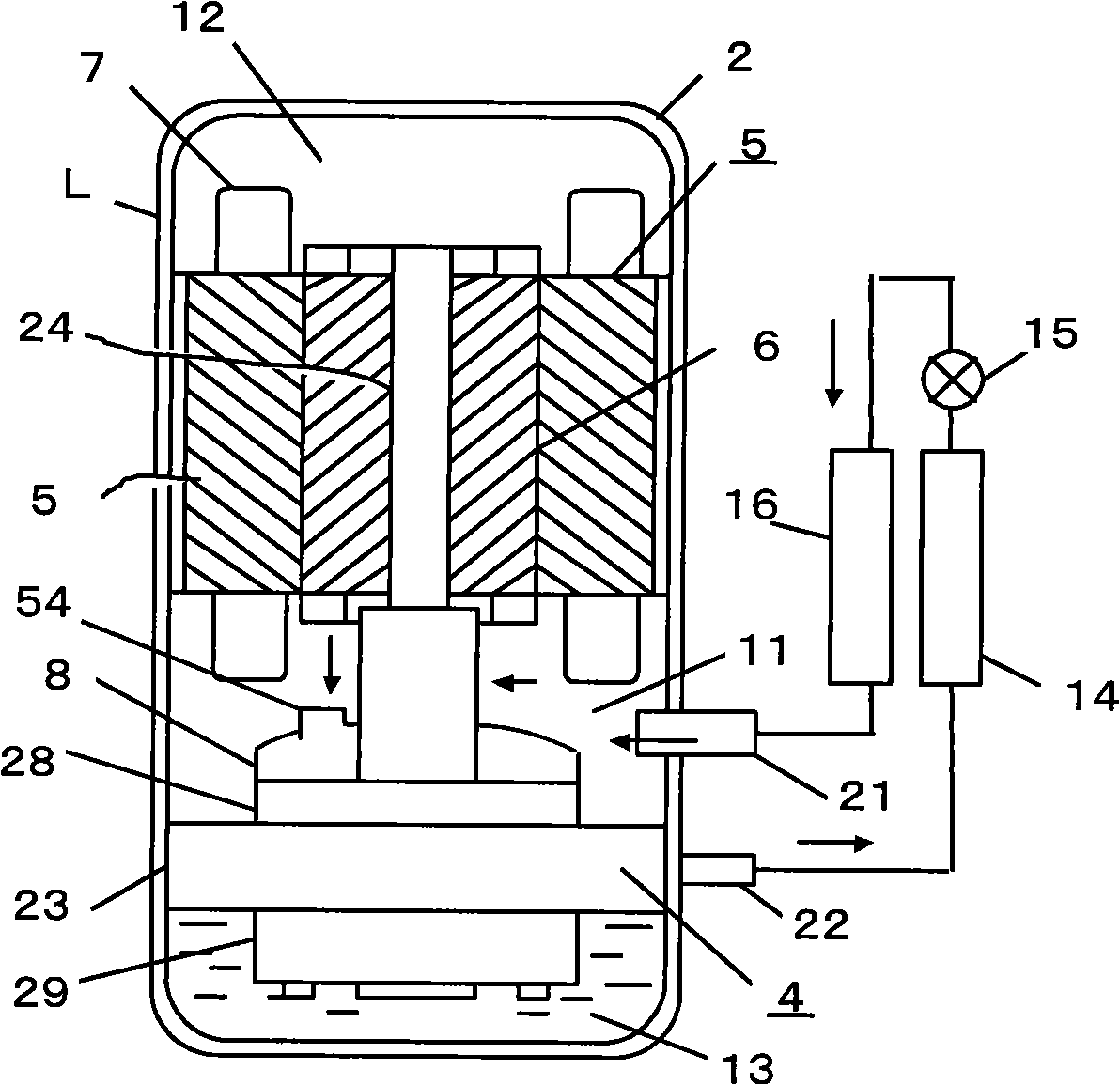
[0027] The following is based on figure 1 The form of the first embodiment of the present invention will be described. figure 1 The schematic structure of the rotary compressor of this invention and an example of the structure of the system equipped with this compressor are shown. The system can be air conditioner, refrigeration equipment and water heater etc. The internal pressure of the shell of the rotary compressor used in the first embodiment is the same as that of the suction, and both are on the low pressure side, so this compressor can be called a rotary compressor L with low shell back pressure.

[0028] A motor 3 is arranged in the sealed casing 2 of the rotary compressor L with low casing back pressure, and a compression assembly 4 of the compressor is arranged below it, and they are fixed inside the casing 2 . The motor 3 consists of a stator 5 with motor windings and a rotor 6 . There is a suction muffler 8 at the top of the compression assembly 4 of the compre...

no. 2 example

[0043] In the second embodiment of the present invention, the internal pressure of the casing of the rotary compressor is the same as the discharge of the compressor, which is on the high pressure side. This compressor may be referred to as a shell high pressure rotary compressor H. The difference between the second embodiment of the present invention and the first embodiment will be mainly described below.

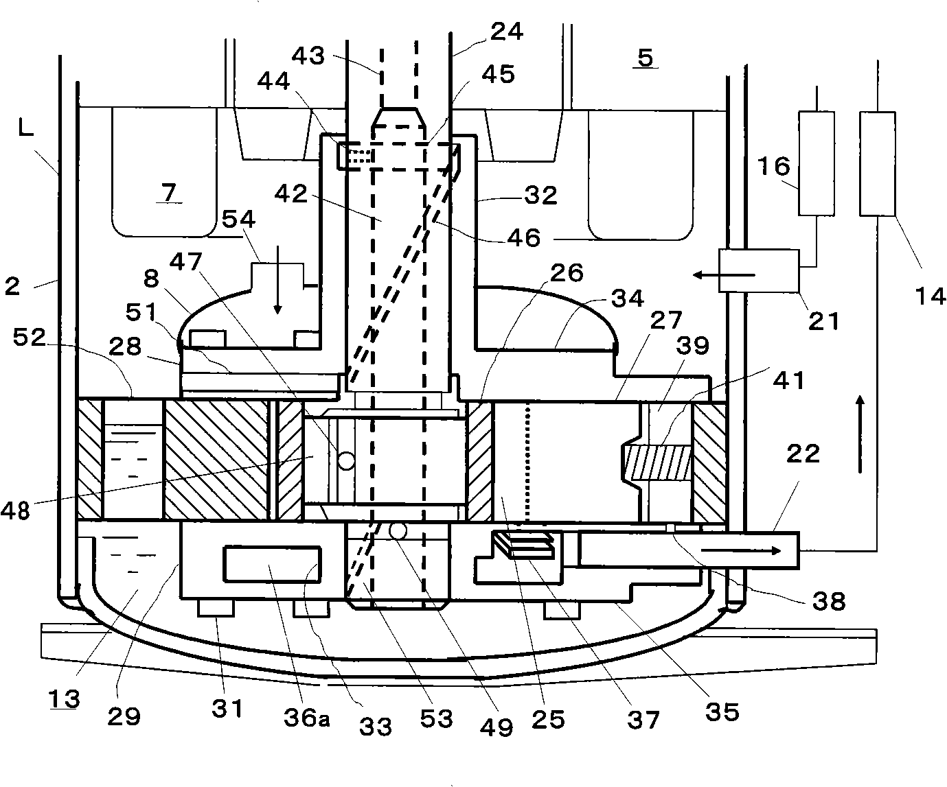
[0044] see Figure 5-Figure 6 , In the high-pressure rotary compressor H of the shell, the side of the compression assembly 4 has a suction pipe 21, the base of the main bearing is provided with an exhaust muffler H 36b, and the upper end of the shell 2 has an exhaust pipe 22. Next, the internal structure of the compressor and the gas flow direction of the system will be described. From the evaporator 16 through the suction pipe 21, the low-pressure gas directly sucked by the cylinder compression chamber 25 is compressed and becomes a high-pressure gas, which is dischar...

no. 3 example

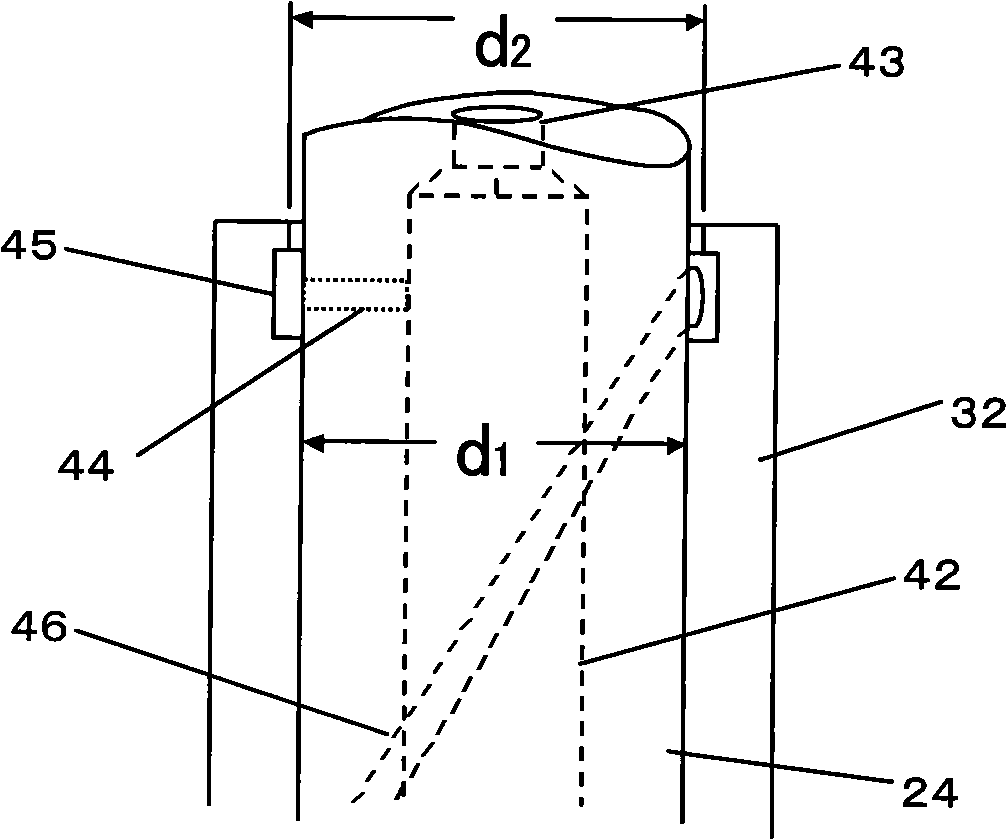
[0053] see Figure 7 , the sleeve pipe 62 is pressed into the vertical hole 43 on the crankshaft. According to this design, it can prevent the oil in the lower vertical hole 42 of the crankshaft from flowing out from the upper end of the crankshaft 24 to the inside of the housing through the upper vertical hole 43 during operation, and can further improve the oil supply effect to the first horizontal hole 44 .


PUM


Abstract

The invention relates to a control method for an oil bleeding reduction device of a rotary compressor and application thereof; the oil bleeding reduction device of the rotary compressor comprises a motor arranged in a shell body of the rotary compressor and a compression component connected with the motor, wherein, the compression component comprises a cylinder, a sliding vane, a crank shaft, a main bearing and a supplementary bearing; the main bearing and the supplementary bearing are used for supporting the crank shaft; the crank shaft is internally provided with a vertical core of an oil pool opening facing to the bottom of the rotary compressor; the vertical core comprises a lower crank shaft vertical core and an upper crank shaft vertical core connected with the lower crank shaft vertical core; the upper crank shaft vertical core is arranged at the upper end of the crank shaft; a long bearing sheathed with the crank shaft is arranged above the main bearing; an inner circular groove is arranged around the upper part of the long bearing circumferentially; the crank shaft arranged at the upper part of the lower crank shaft vertical core is provided with a first cross bore; one end of the first cross bore is open in the lower crank shaft vertical core, while the other end thereof is open in the position of the inner circular groove; the inner diameter of the top of the long bearing positioned above the inner circular groove is 10 microns to 20 microns larger than that of the long bearing.

Description

technical field [0001] The invention relates to a rotary compressor, in particular to a control method and application of a rotary compressor oil discharge reduction device, which is mainly suitable for Freon refrigerants represented by HCFC and HFC, or CO 2 , HC is a rotary compressor used in natural refrigerant air conditioners, refrigeration equipment, or water heaters. Background technique [0002] In recent years, as rotary compressors have become popular all over the world, in order to improve the energy efficiency of refrigeration systems and the reliability of compressors, there has been an increasing demand for reducing the amount of circulating oil discharged from rotary compressors to the system as much as possible. . In rotary compressors, the above-mentioned circulating oil discharge volume is large and difficult to control is a big problem. Especially in rotary compressors with low shell back pressure, reducing the circulating oil discharge volume is the bigge...

Claims


Application Information

Patent Timeline
Patent Type & Authority Applications(China)
IPC IPC(8): F04C29/02F04C29/00F04C19/00
Inventor 陈振华小津政雄高强
Owner GUANGDONG MEIZHI COMPRESSOR
Why Eureka
Try Eureka