Counter circuit structure and electronic device using the same

A technology of circuit structure and electronic device, which is applied to pulse counters, counting chain pulse counters, electrical components, etc., can solve the problems of increasing the area and power consumption of integrated circuit chips, and achieve the reduction of area and power consumption, simplification of circuit structure, The effect of reducing dosage

Active Publication Date: 2009-01-28
HOLTEK SEMICON
View PDF0 Cites 6 Cited by
  • Summary
  • Abstract
  • Description
  • Claims
  • Application Information

AI Technical Summary

Problems solved by technology

[0007] The above-mentioned prior art counter circuit structure 1 must be realized by using one counter module 10 and two buffer modules 12, 14, therefore, when the number of bits increases, the number of logic circuit components used therein will increase three times with the number of bits , causing the area and power consumption of the integrated circuit chip occupied by the counter circuit structure 1 to increase at the same time

Method used


Image

  • Counter circuit structure and electronic device using the same
  • Counter circuit structure and electronic device using the same
  • Counter circuit structure and electronic device using the same

Examples


Embodiment Construction

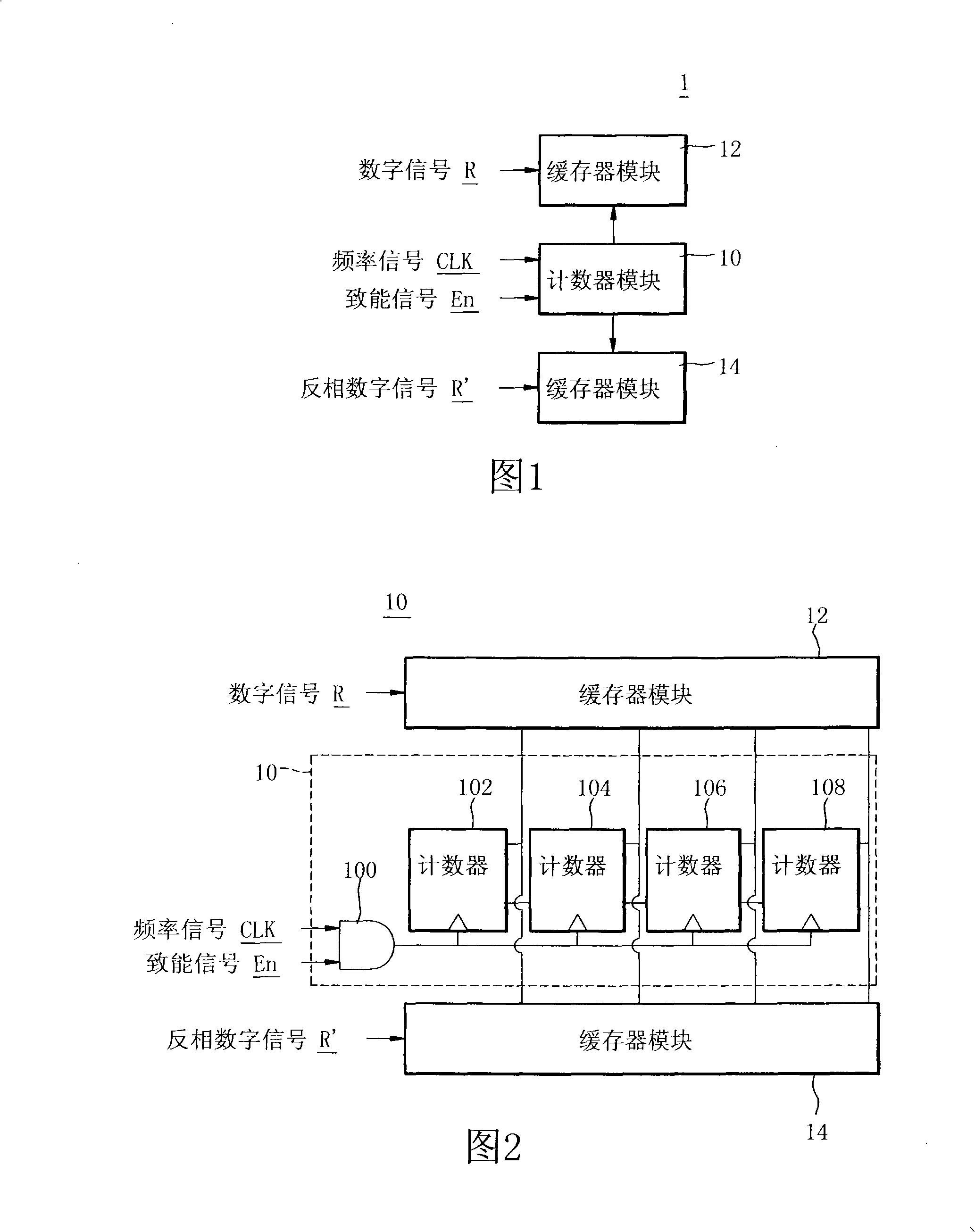
[0045] The present invention is based on the fact that the counter composed of flip-flops has the function of temporarily storing values. Therefore, for the continuous two-phase counting of signals, two sets of counters are used to calculate the high level (logic value = 1) and low level respectively. The signal width of the level (logic value=0) is used to simplify the structure of the counter circuit in the prior art.

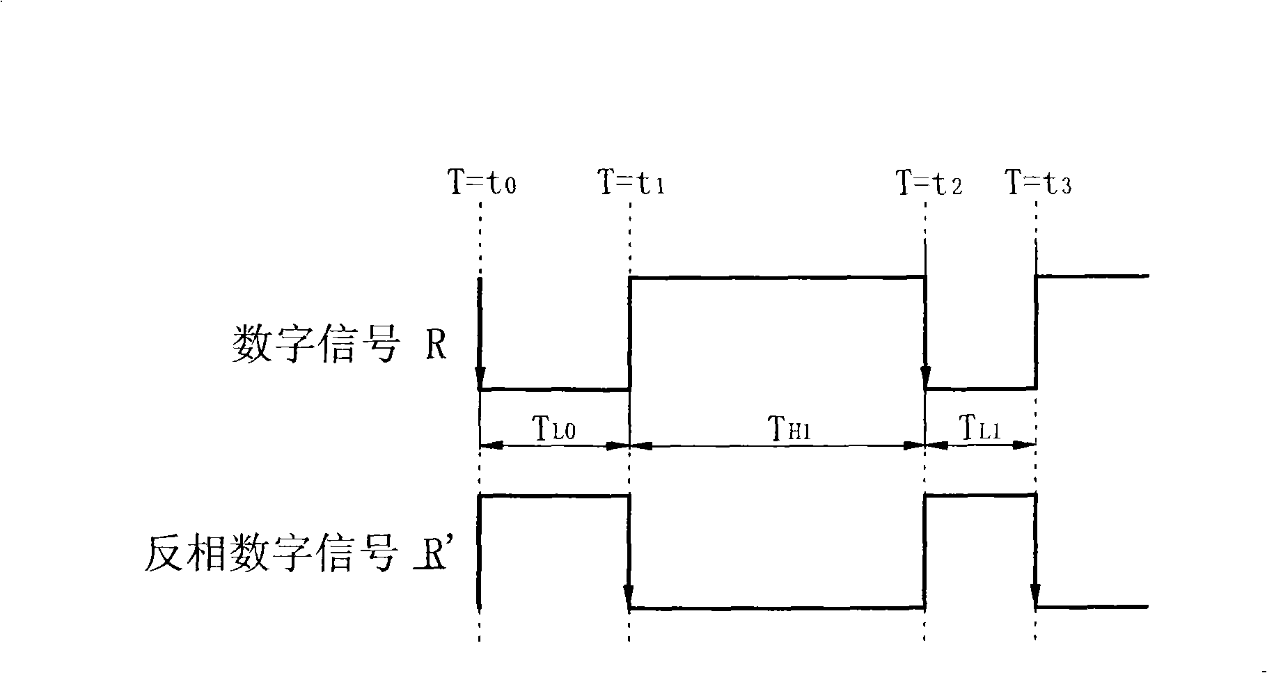
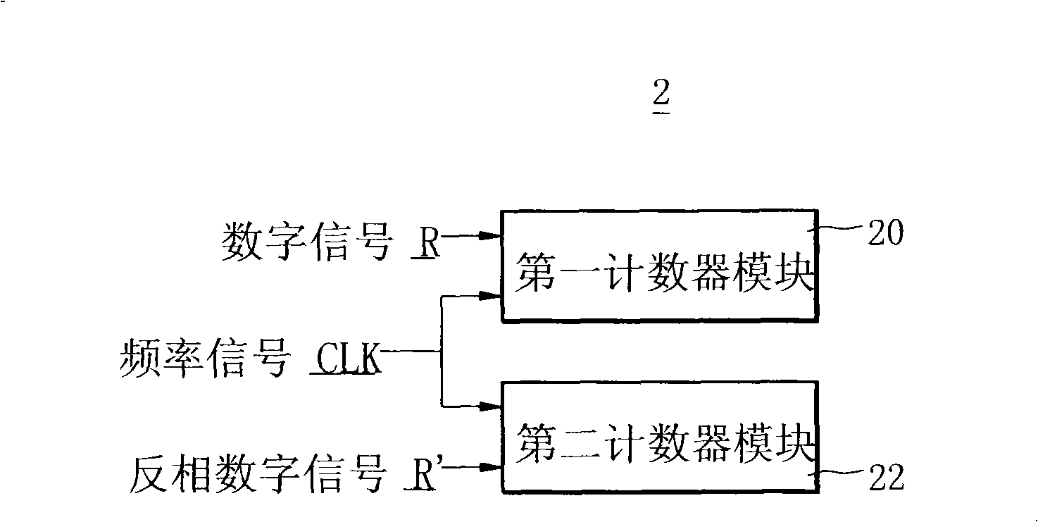
[0046] First, see Figure 4 , which is a schematic diagram of the system structure of the counter circuit structure 2 of the present invention. This counter circuit structure 2 is suitable for calculating the number of cycles of a digital signal R relative to a frequency signal Clk, the signal type of the digital signal R refers to a non-return to zero (Non-return to zero, NRZ) code, which It is composed of continuous high level (logic value=1) signal and low level (logic value=0) signal.

[0047] Such as Figure 4 As shown, the counter circuit structure 2...


PUM


Abstract

The invention discloses a circuit structure for a counter and an electronic device applied to the circuit structure for the counter. The circuit structure for the counter and the electronic device are suitable for calculating the periodicity of one digital signal relative to one frequency signal, wherein the signal modal of the digital signal is a nonreturn-to-zero code. The circuit structure for the counter comprises a first counter module and a second counter module, wherein the first counter module receives the digital signal and the frequency signal; when the digital signal is in a high level, the first counter module calculates the periodicity of the signal width of the digital signal relative to the frequency signal; the second counter module receives an inverted signal of the digital signal and the frequency signal; and when the inverted signal of the digital signal is in a high level, the second counter module calculates the periodicity of the signal width of the inverted signal of the digital signal relative to the frequency signal. The counter circuit has a simplified structure, reduces the use amount of the components of a logic circuit, further reduces the occupied area of the circuit structure, lowers the power consumption, and facilitates the application of the integrated circuit.

Description

technical field [0001] The invention relates to a counter circuit structure, in particular to a counter circuit structure suitable for calculating the signal width of a digital signal, and an electronic device for its application. Background technique [0002] In digital logic circuits, the circuit structure of a counter (Timer counter) is a circuit type that is widely used. Counter circuits are often used in decoding systems as signal width calculators for digital signals. Please refer to FIGS. 1, 2, and 3. FIG. 1 and FIG. 2 are schematic diagrams of a system structure of a counter circuit structure 1 in the prior art, and FIG. 2 is a schematic diagram of a circuit structure of the counter module 10 in FIG. 1 . image 3 It is a timing diagram of the digital signal R and the inverted digital signal R'. The counter circuit structure 1 shown in Figs. 1 and 2 is suitable for calculating the signal width of the digital signal R. [0003] The signal type of the digital signal R...

Claims


Application Information

Patent Timeline
Patent Type & Authority Applications(China)
IPC IPC(8): H03K23/00
Inventor 郑文平杨千柏
Owner HOLTEK SEMICON
Why Eureka
Try Eureka