Electrically bent endoscope device
An endoscope, bending technology, applied in the field of electric bending endoscope device
- Summary
- Abstract
- Description
- Claims
- Application Information
AI Technical Summary
Problems solved by technology
Method used
Image
Examples
Embodiment 1
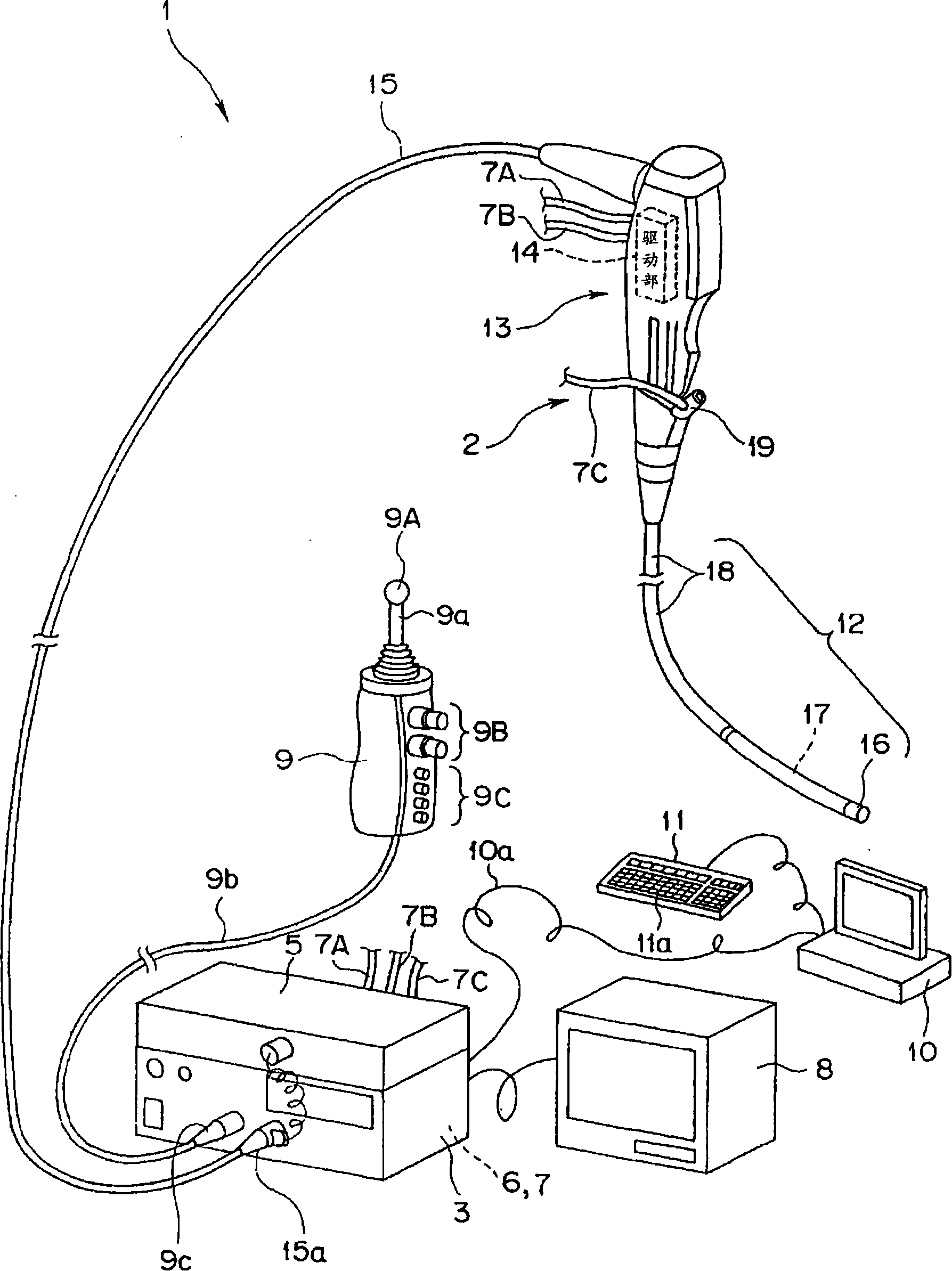
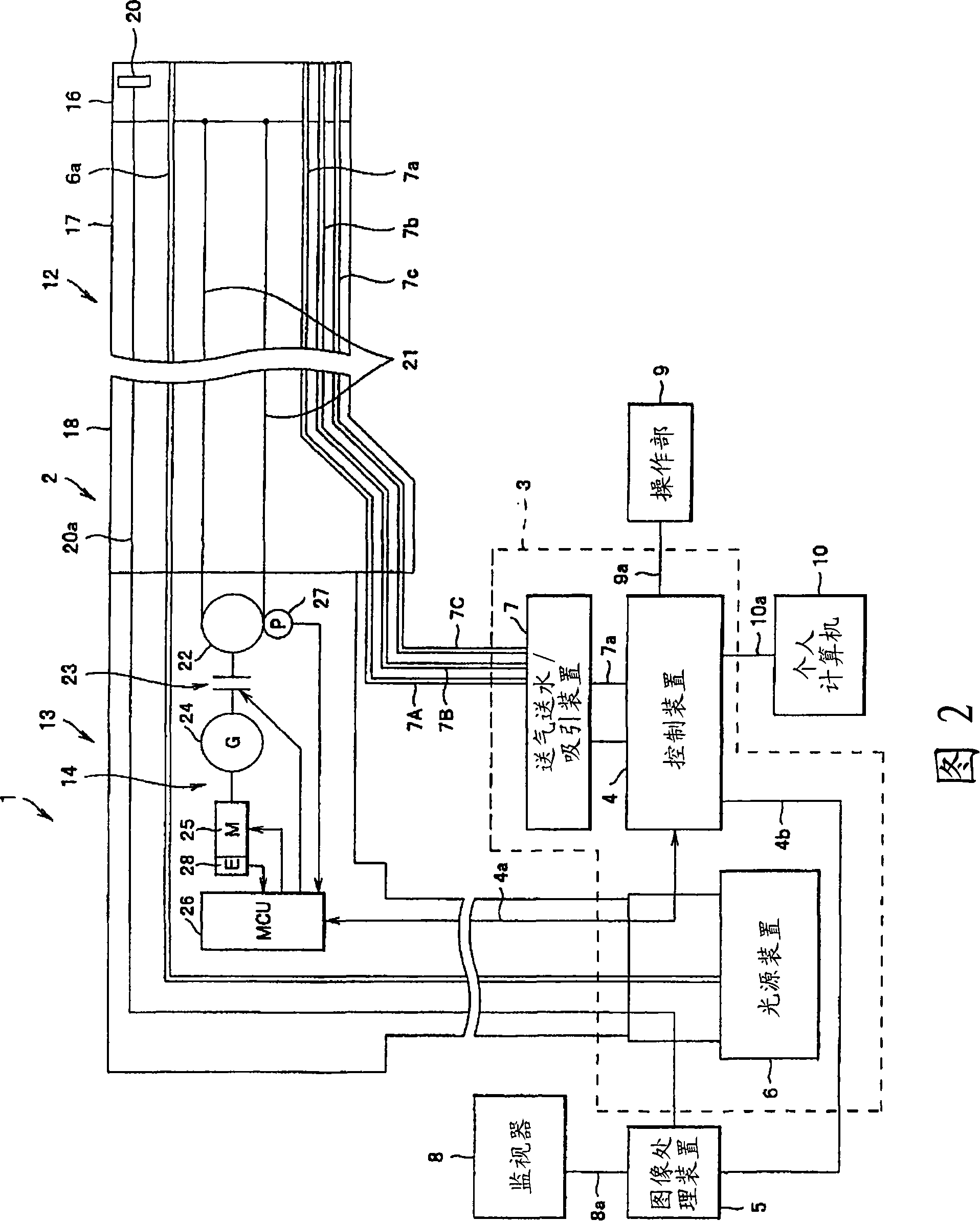
[0051] figure 1 and figure 2 Embodiment 1 of the electric bending endoscope device of the present invention will be described. figure 1 It is a system configuration diagram of the electric bending endoscope device. figure 2 is showing figure 1 A diagram of the schematic structure of the motorized bending endoscope device.
[0052] Such as figure 1 and figure 2 As shown, the electric bending endoscope device 1 of embodiment 1 has: electric bending endoscope (hereinafter referred to as endoscope for short) 2; Control unit 3; The image signal transmitted by the signal cable 20a extending from the above-mentioned imaging element 20 is generated as an image signal; the monitor 8 as a display device outputs the image signal generated by the above-mentioned image processing device 5, and displays an endoscopic image; 9, which is electrically connected to the above-mentioned control unit 3; and a personal computer (hereinafter referred to as PC) 10 as a setting value inpu...
Embodiment 2
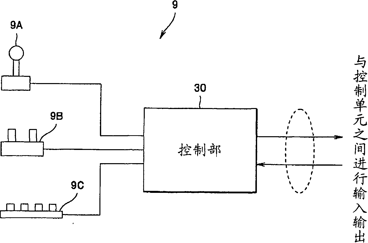
[0210] Figure 23 to Figure 27 It relates to Embodiment 2 of the electric bending endoscope device of the present invention. Figure 23 It is a block diagram showing the configuration of the control unit provided in the operation unit. Figure 24 is showing Figure 23 A block diagram of the specific structure of the signal processing section of the bending instruction section. Figure 25 is used to pass based on the Figure 23 An explanatory diagram of the angle mode described later for setting the operation unit through the judgment process of the information of the identification ID. Figure 26 It is an electric signal coordinate diagram of the bending instruction part instruction signal after the signal processing in the game mode mentioned later. Figure 27 It is the electrical signal coordinate diagram of the indication signal of the bending indication part after the signal processing in the angle knob mode. also, Figure 23 and Figure 24 The same reference numera...
Embodiment 3
[0227] Figure 28 and Figure 29 It relates to Embodiment 3 of the electric bending endoscope device of the present invention. Figure 28 It is a block diagram showing the configuration of the control unit provided in the operation unit. Figure 29 is showing Figure 28 A block diagram of the specific structure of the signal processing section of the bending instruction section. also, Figure 28 and Figure 29 The same reference numerals are assigned to the same structural elements as in the above-mentioned embodiment 2, and descriptions are omitted, and only different parts will be described.
[0228] In this example, if Figure 28 As shown, a reference voltage signal (also referred to as a Ref reference voltage signal) as a reference from the above-mentioned bending instruction unit 9A is input to the bending instruction unit signal processing unit 31 .
[0229] That is, if Figure 29 As shown, the above-mentioned Ref reference voltage signal is input to the A / D conv...
PUM
 Abstract
Description
Claims
Application Information
 - R&D
- Intellectual Property
- Life Sciences
- Materials
- Tech Scout
- Unparalleled Data Quality
- Higher Quality Content
- 60% Fewer Hallucinations
Browse by: Latest US Patents, China's latest patents, Technical Efficacy Thesaurus, Application Domain, Technology Topic, Popular Technical Reports.
© 2025 PatSnap. All rights reserved.Legal|Privacy policy|Modern Slavery Act Transparency Statement|Sitemap|About US| Contact US: help@patsnap.com


