
High temperature resistant fibres

A high-temperature-resistant fiber technology, applied in the field of high-temperature-resistant fibers, can solve problems such as difficult to find, uncontrolled crystallization, and difficult melt formation

Inactive Publication Date: 2009-01-28
THE MORGAN CRUCIBLE CO PLC
View PDF35 Cites 13 Cited by
  • Summary
  • Abstract
  • Description
  • Claims
  • Application Information

AI Technical Summary

Problems solved by technology

[0035] a) Melt formation becomes increasingly difficult with increasing melt temperature and uncontrolled crystallization may occur
[0036] b) Because higher melt temperatures are required, it is difficult to find materials for devices with reasonable service life at the temperatures involved

Method used


Image

  • High temperature resistant fibres
  • High temperature resistant fibres
  • High temperature resistant fibres

Examples


Embodiment Construction

[0067] Other features and aspects of the invention will be apparent from the claims and the following exemplary description, with reference to the accompanying drawings, in which:

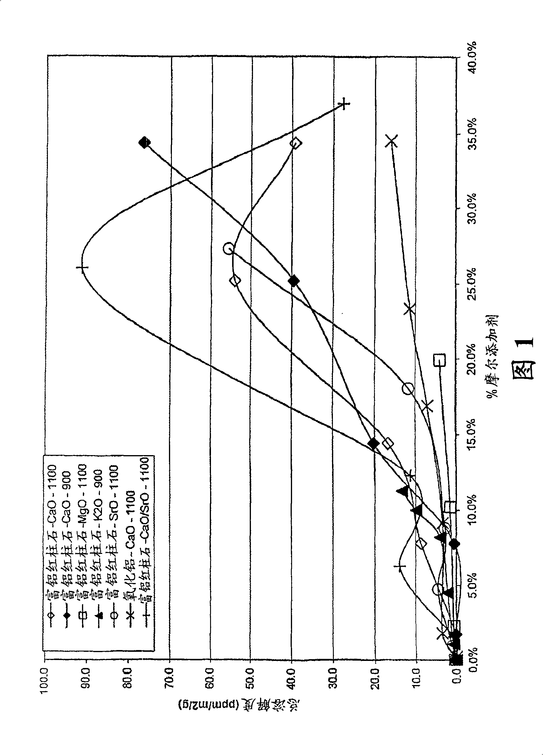
[0068] Figure 1 is a graph of the solubility in body fluids of a series of fibers including the fibers of the present invention.

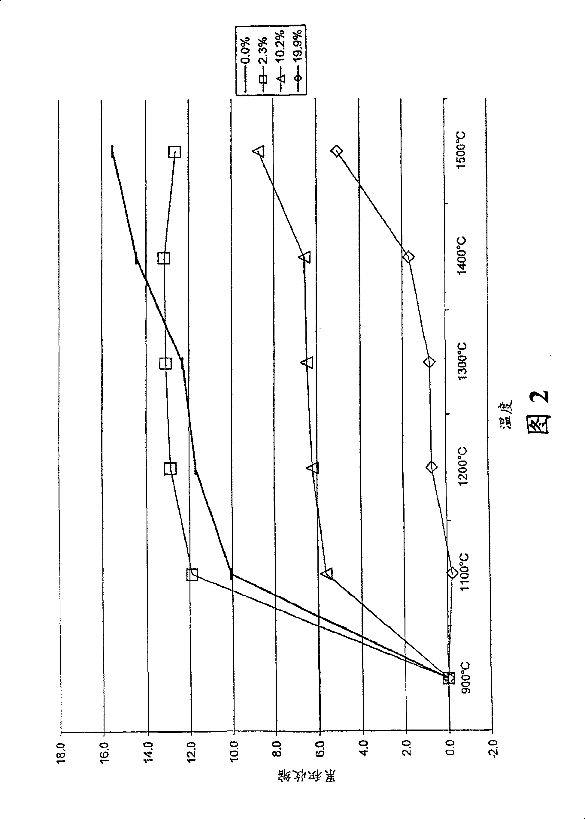
[0069] Figure 2 is a graph of shrinkage versus temperature for a series of MgO-modified mullite matrix composition fibers.

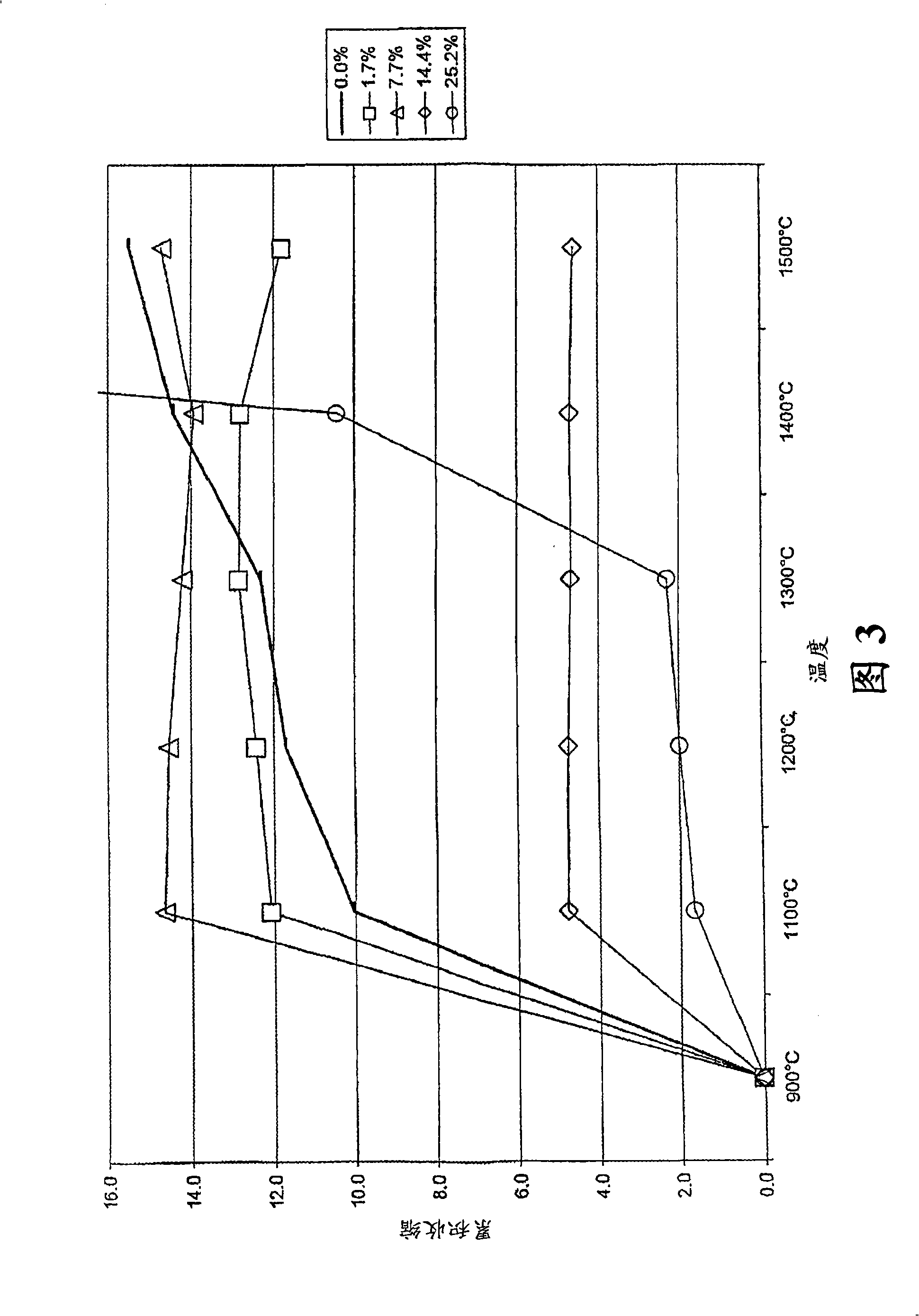
[0070] Figure 3 is a graph of shrinkage versus temperature for a series of CaO-modified mullite matrix composition fibers.

[0071] Figure 4 is a graph of shrinkage versus temperature for a series of SrO-modified mullite matrix composition fibers.

[0072] Figure 5 is a graph of shrinkage versus temperature for a series of CaO and SrO modified mullite matrix composition fibers.

[0073] Figure 6 is a graph of shrinkage versus temperature for a series of fibers of a CaO-modified alumina matrix composition.

[0074] Figure 7 is a graph showing th...


PUM


Abstract

Thermal insulation comprises sol-gel formed fibres comprising 10 to 99mol% of a refractory base composition, and 1 to 90mol% of a component selected from alkaline earth metal oxides, alkali metal oxides, and mixtures thereof, and wherein said alkaline earth metal oxides if present comprise one or more of calcium oxide, strontium oxide, barium oxide or a mixture thereof. The refractory base comprises SiO2 and A12O3.

Description

field of invention [0001] The present invention relates to high temperature resistant fibers produced by the sol-gel method. Such fibers are used particularly (but not exclusively) as thermal insulation. The invention also relates to the use of such fibers in catalyst bodies support structures in pollution control equipment, such as automotive exhaust system catalytic converters and diesel particulate filters. Background of the invention [0002] The use of fibrous materials as thermal insulation materials is known, as is the use of fibrous materials as reinforcing components in composite materials (eg fiber reinforced cements, fiber reinforced plastics) and as components of metal matrix composites. [0003] Prior to 1987, there were four main fiber materials used to make thermal insulation products [eg blankets, vacuum formed shapes and mastics]. These fiber materials are produced through two main production lines, the details of which will vary depending on the manufactu...

Claims


Application Information

Patent Timeline
IPC IPC(8): C03C13/00C04B35/624
CPCC04B2235/3418C04B2235/3206C04B2235/444C04B2235/3201C04B2235/5264C04B2235/9692C04B2235/526C04B35/62245F01N3/2853C04B2235/3208C04B2235/5454C04B35/62236C04B2235/3213F01N13/14C04B2235/483C04B35/63408D04H1/4209C04B35/624
Inventor R·C·万赖特D·H·托马斯S·P·奥利弗
Owner THE MORGAN CRUCIBLE CO PLC
Learn More