Hollow mold for filling cast-in-situ concrete

A hollow carcass, cast-in-place concrete technology, applied in the direction of floor slabs, building materials, building components, etc., to achieve the effects of simple construction, light structure, and improved overall performance

Inactive Publication Date: 2009-02-04
湖南邱则有专利战略策划有限公司
View PDF3 Cites 1 Cited by
  • Summary
  • Abstract
  • Description
  • Claims
  • Application Information

AI Technical Summary

Problems solved by technology

In this way, since the corner where at least two surfaces intersect is an arc angle or a chamfer or a negative angle or a combination thereof, the stress concentration phenomenon at the corner of the hollow carcass in the hollow plate can be effectively eliminated, cracks can be prevented, and it can withstand relatively high pressure. The large concentrated load acts without damage, improving the mechanical properties of the hollow slab; at the same time, since at least one support foot is connected to the outer wall of the laminated layer containing the prefabricated cast-in-place laminated layer, the laminated layer contains the cast-in-place layer and the prefabricated layer, Therefore, the connection between the support foot and the hollow carcass is firm, the strength is high, and the rigidity is large. During the handling process, the breakage of the support foot and the joint with the hollow carcass is not easy to occur, thereby better solving the problems existing in the prior art. , achieved the purpose of the present invention; in addition, the hollow carcass also has the characteristics of simple structure, high strength, high rigidity, excellent deformation resistance, vibration resistance, and fast construction speed, and is suitable for cast-in-place reinforced concrete or prestressed reinforced concrete. Hollow slabs, floors, roofs, walls, foundation slabs and bridges, especially for hollow beamless floors

Method used


Image

  • Hollow mold for filling cast-in-situ concrete
  • Hollow mold for filling cast-in-situ concrete
  • Hollow mold for filling cast-in-situ concrete

Examples


Embodiment Construction

[0078] The present invention will be further described below in conjunction with the accompanying drawings and embodiments.

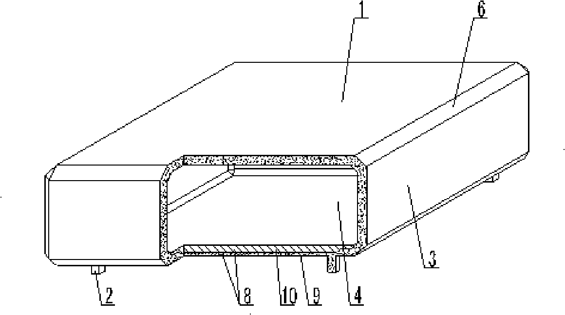
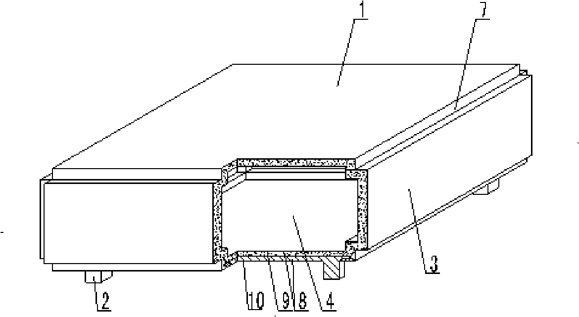
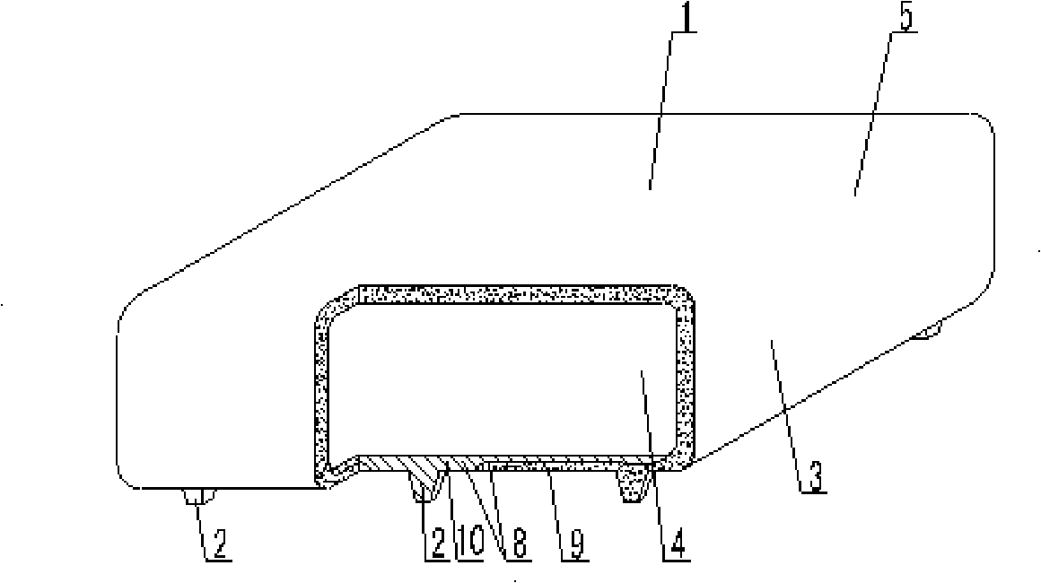
[0079] As shown in the accompanying drawings, the present invention includes a hollow carcass 1 and a support foot 2. The support foot 2 is arranged on the outer wall 3 of the bottom surface of the hollow carcass 1, and the outer wall 3 encloses the hollow carcass 1 with a cavity 4. Its characteristics The corner where the at least two surfaces intersect is an arc angle 5 or a chamfer 6 or an inner corner 7 or a combination thereof, and at least one support foot 2 is connected to the outer wall 3 containing a prefabricated cast-in-place laminated laminated layer 8, and the laminated The composite layer 8 includes a cast-in-place layer 9 and a prefabricated layer 10 , reinforcements 14 are arranged in the embryo body of the outer wall 3 , and reinforcements 18 are arranged in the cavity 4 . In each drawing, 1 is the hollow carcass, 2 is the support foot,...


PUM


Abstract

A hollow matrix for filling cast-in-place concrete includes a hollow matrix (1) and an arm brace (2). The arm brace (2) is arranged on the outside wall (3) of the bottom of the hollow matrix (1). The outside wall (3) circles to form the hollow matrix (1) with a cavity (4). The invention is characterized in that the corner caused by the intersection of at least two sides is an arc angle (5) or a chamfer angle (6) or an internal corner (7) or the combination of the angles. At least one arm brace (2) is connected with the outside wall (3) of a superposed layer (8) including prestressed cast-in-place superposition. The superposed layer (8) includes a cast-in-place layer (9) and a prefabricated layer (10). An enhancer (14) is arranged in the base body of the outside wall (3) and a reinforcement (18) is arranged in the cavity (4).The hollow matrix is appliable to the cast-in-place reinforced concrete or the hollow slab, the floor system, the roof system, the wall and the base soleplate of the prestressed concrete and bridges, which is especially applicable to hollow girderless floor system.

Description

[0001] This application is a divisional application of an invention patent application with an application date of September 2, 2004, an application number of 200410155279.7, and a title of "a hollow matrix for filling cast-in-place concrete". (1) Technical field [0002] The invention relates to a hollow matrix for filling cast-in-place concrete. (2) Background technology [0003] At present, the cast-in-place concrete hollow floor is a widely used floor structure. The lightweight permanent tire molds filled in it include various hollow tubes and boxes, and the boxes are hollow or solid. For example, the patent No. ZL99249798.1, which the applicant applied for on November 29, 1999, is a utility model patent named "fiber-reinforced thin-walled member for reinforced concrete filling", which discloses a thin-walled formwork member, including an upper plate, The surrounding side walls, the lower bottom, and the upper plate, the surrounding side walls and the lower bottom form a...

Claims


Application Information

Patent Timeline
Patent Type & Authority Applications(China)
IPC IPC(8): E04C1/00E04C1/39E04C1/40E04B5/36E04B5/18
Inventor 邱则有
Owner 湖南邱则有专利战略策划有限公司
Why Eureka
Try Eureka