Synchronization triggering on-line diagnostic method and system for photoetching machine

A technology for synchronizing triggering and diagnosing systems, applied in microlithography exposure equipment, photolithography process exposure devices, etc., can solve the problems of asynchronous data timing, inability to locate synchronous timing, and inability to quickly locate lithography machine problems, etc. Achieve the effect of rapid positioning, saving time for integration and technical support

Active Publication Date: 2010-12-08
SHANGHAI MICRO ELECTRONICS EQUIP (GRP) CO LTD
View PDF1 Cites 1 Cited by
  • Summary
  • Abstract
  • Description
  • Claims
  • Application Information

AI Technical Summary

Problems solved by technology

[0006] 1. The usual data diagnosis system is independent of each subsystem and cannot systematically locate the problem
[0007] 2. Unable to locate some synchronization timing problems, such as the problem of out-of-sync data timing between modules of different subsystems
[0008] 3. The diagnostic data of different subsystems cannot be strictly matched one by one according

Method used


Image

  • Synchronization triggering on-line diagnostic method and system for photoetching machine
  • Synchronization triggering on-line diagnostic method and system for photoetching machine
  • Synchronization triggering on-line diagnostic method and system for photoetching machine

Examples


Example Embodiment

[0036] According to Figure 1 ~ Figure 3 , Specifically describe the preferred embodiments of the present invention:

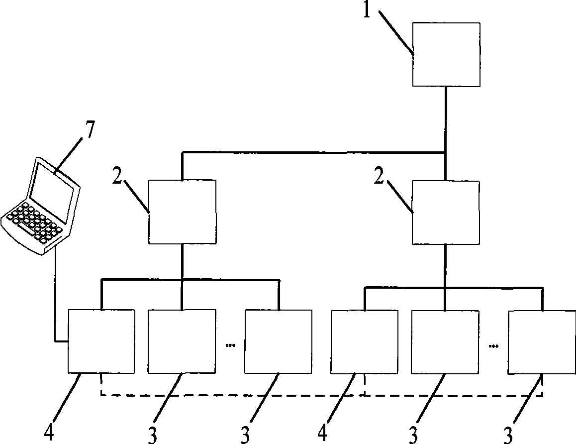
[0037] Such as figure 1 As shown, the present invention provides a lithography machine synchronous trigger diagnosis system including two sub-systems, including: a main controller 1; two sub-system controllers 2; two trigger diagnosis buffer boards 4; three sub-systems System control daughter card 3.

[0038] Such as figure 1 In the system shown, the trigger diagnostic buffer board 4 exists in each sub-system of the lithography machine system, and the trigger diagnostic buffer board 4 and the sub-system controller 2 and the sub-system control sub-card 3 and the sub-system control sub-card 3 They are connected via a standard VME bus. The trigger diagnosis buffer board 4 is connected through a hardware synchronization signal line. These trigger diagnostic buffer boards provide a special ring buffer for storing the diagnostic data on the sub-system controller 2 and...


PUM


Abstract

A lithography machine synchronous trigger online diagnosis method and a system thereof are composed of a controller, subsystem controllers, a portable PC, trigger diagnosis buffer plates, subsystem control slave cards, as well as the corresponding processing software. The trigger diagnosis buffer plate provides an annular buffer area to store all the diagnostic data of each subsystem; and the trigger diagnosis buffer plates are connected with each other through hardware synchronization signal lines. The trigger diagnosis system collects the diagnostic data of precise time sequences of all thesubsystems and does not affect the normal operation of the systems at the same time, so as to help positioning the problems rapidly and reduce the integration and on-site technical support time.

Description

technical field [0001] The invention relates to the technical field of scanning photolithography machines, in particular to the technical field of synchronous control of scanning photolithography machines. Background technique [0002] Lithography machines can generally be divided into two types: stepper lithography machines and scanning lithography machines. Among them, stepper lithography machines use one-time imaging technology. In order to increase the image field, a larger diameter lens system is required as a support. Due to the dual constraints of existing technology and economic cost, the application of stepper lithography is limited, and it can no longer meet the development direction of higher precision and larger size of chip processing technology. [0003] As a result, a new type of scanning lithography machine was produced. The biggest feature of the scanning lithography machine is the synchronous scanning function. The exposure process of a scanning lithograph...

Claims


Application Information

Patent Timeline
IPC IPC(8): G03F7/20
Inventor 周金明池峰黄芳
Owner SHANGHAI MICRO ELECTRONICS EQUIP (GRP) CO LTD
Why Eureka
Try Eureka