Electronic label reading and writing device antenna and a RFID system

A technology of electronic tags and readers, which is applied in the direction of antennas, antenna arrays, antenna supports/installation devices, etc., can solve the mismatch between the antenna port of the reader and the antenna, the unpredictable radiation field of the antenna, and the inability to communicate with electronic tags, etc. problems, to achieve the effect of flexible production, little impact on the installation environment, and convenient installation

Active Publication Date: 2009-02-04
CHINA ELECTRONICS TECH GRP NO 7 RES INST
View PDF0 Cites 19 Cited by
  • Summary
  • Abstract
  • Description
  • Claims
  • Application Information

AI Technical Summary

Problems solved by technology

[0006] If in a very narrow space, and at least three sides of the space are surrounded by large areas of metal (such as metal cabinets), when reading multiple passive UHF frequency band RFID electronic tags in a small space , the metal has a strong reflection effect on the electromagnetic waves emitted by the reader. Usually, the indicators of the supporting antenna of the reader will change greatly, especially the VSWR (Voltage Standing Wave Ratio, voltage standing wave ratio) of the antenna port. Rapid deterioration, resulting in a mismatch between the antenna port of the reader and the antenna, and the failure to communicate with the electronic tag normally
And because the electromagnetic waves emitted by the reader are reflected multiple times in a small range in an environment covered by multiple metals, the radiation field of the antenna becomes unpredictable
Through some tests, it is found that there will be some dead zones in this environment, that is, the electronic tag cannot receive the electromagnetic wave energy emitted by the reader at all.

Method used


Image

  • Electronic label reading and writing device antenna and a RFID system
  • Electronic label reading and writing device antenna and a RFID system
  • Electronic label reading and writing device antenna and a RFID system

Examples


Embodiment 1

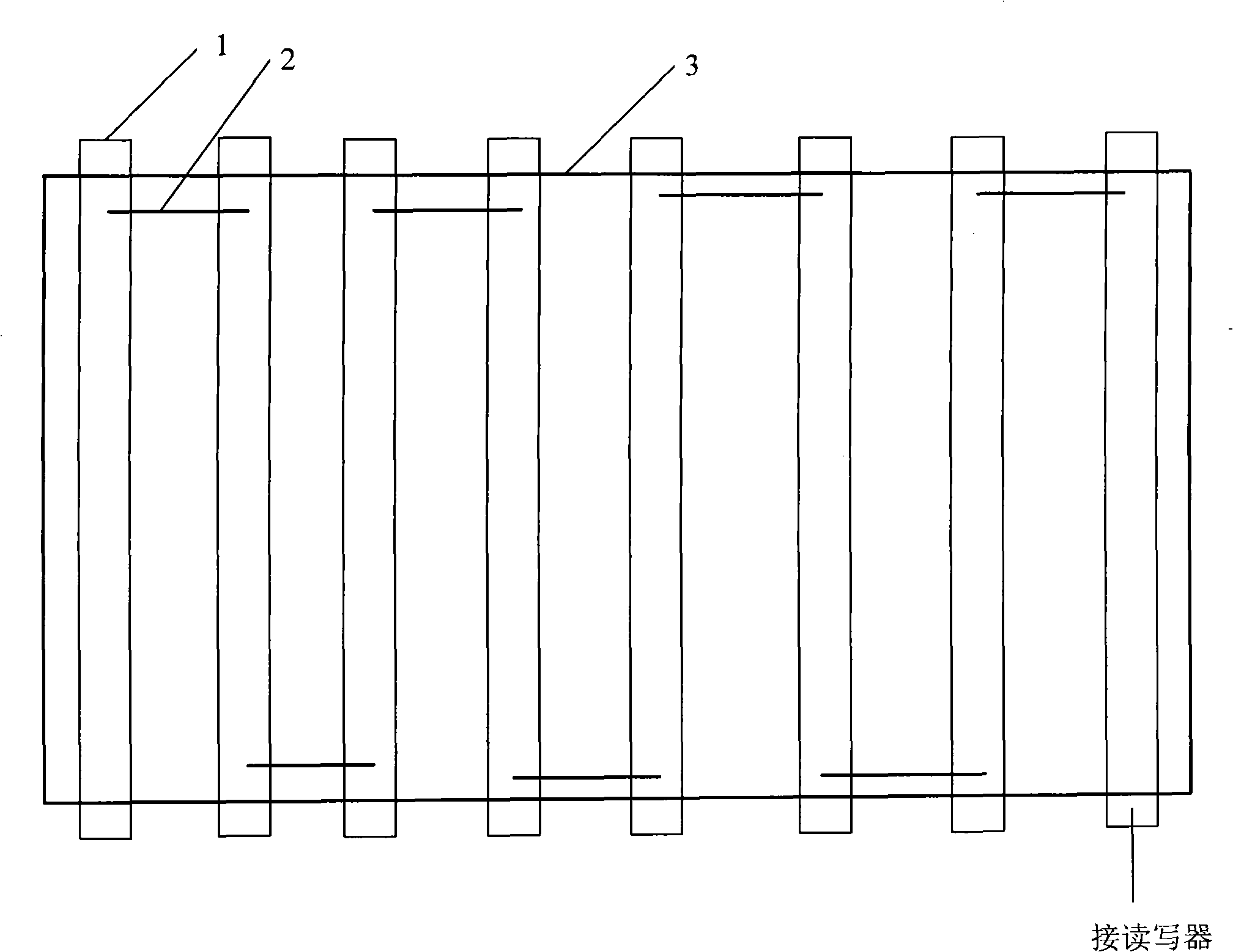
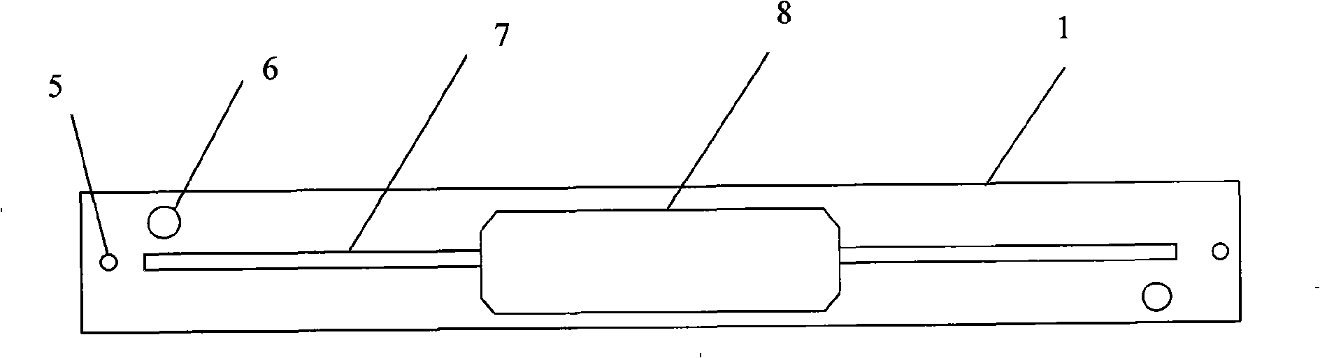
[0022] The electronic tag reader-writer antenna of the present invention is used to connect with the reader-writer. The reader-writer transmits UHF ultra-high frequency radio frequency signals through the antenna to activate the electronic tag to communicate with the reader-writer. The electronic tag reader-writer antenna of the present invention It consists of one antenna radiating unit or a plurality of antenna radiating units connected in series. The front side of the antenna radiating unit is provided with a microstrip line, and the back side is correspondingly provided with a ground plane. In a specific embodiment, the antenna radiating unit may be a printed circuit board, a microstrip line is provided on the front side of the printed circuit board, and a ground plane is correspondingly provided on the back side of the printed circuit board.

[0023] In a specific embodiment, such as figure 1 , the antenna of the electronic tag reader of the present invention is composed ...

Embodiment 2

[0047] The invention also discloses an RFID system, which includes a reader-writer and an antenna connected to the reader-writer. The reader-writer transmits a UHF ultra-high frequency radio frequency signal through the antenna to activate the electronic tag to communicate with the reader-writer. In this embodiment, the principle structure of the antenna in the RFID system is the same as that of the antenna in Embodiment 1, which will not be repeated here.

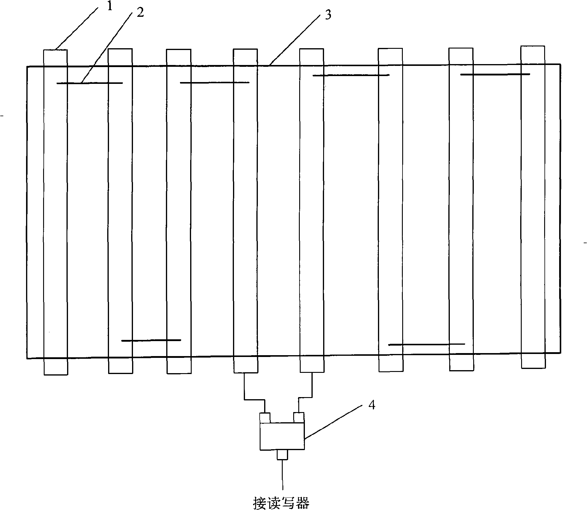
[0048] Since the antenna includes at least one antenna radiating unit, when the antenna is used in series by multiple antenna radiating units, the radiation power of the reader-writer obtained by the antenna radiating unit at the end will be very small, which will affect the identification efficiency of the electronic tag. The electronic tags near the antenna radiation unit will not be able to communicate with the reader stably and correctly. As an improvement, in a specific embodiment, the RFID system of the present inven...

Embodiment 3

[0050] The present invention also discloses a cabinet for carrying equipment with electronic labels. An antenna is fixed on the inner wall of the cabinet. The antenna is used to connect with a reader, and the reader transmits superhigh Frequency radio frequency signal activates the electronic tag to communicate with the reader; the antenna includes an antenna radiating unit provided with a microstrip line and a ground plane, and the microstrip line and the ground plane are correspondingly arranged on the front of the antenna radiating unit And on the back, the antenna radiating unit can be one or more. In this embodiment, the principle and structure of the antenna in the cabinet carrying the electronic tag is the same as that of the antenna in Embodiment 1 and Embodiment 2, and will not be repeated here.

[0051] In this embodiment, the cabinet further includes a power splitter, at least two sections of the antenna are fixed on the inner wall of the cabinet; the input end of t...


PUM


Abstract

The invention discloses an electronic tag reader antenna and an RFID system, wherein, the antenna is used to be connected with a reader, and the reader transmits ultra high frequency radio frequency signals through the antenna for activating an electronic tag to communicate with the reader; the antenna can be composed of an antenna radiating element or a plurality of antenna radiating elements connected in series, the front face of each antenna radiating element is provided with a micro-strip line, and the back face thereof is equipped with a ground plane. The antenna is less influenced by installation environment, and facilitates the flexible making and installation, and is simple and practical, and the antenna can be placed in an extreme narrow space, and the reader can communicate with a plurality of passive UHF frequency band RFID electronic tags placed in the extreme narrow space via the antenna stably and correctly. The antenna and the system particularly solve the problem that the plurality of passive UHF frequency band RFID electronic tags in the narrow space can not be read stably and correctly under the condition that the extreme narrow space is enclosed by large area of metal.

Description

technical field [0001] The invention relates to the technical field of radio frequency identification, in particular to an antenna of an electronic tag reader-writer and an RFID system. Background technique [0002] RFID (Radio Frequency Identification, radio frequency identification) technology, also known as electronic tag technology, is a non-contact automatic identification technology. Its basic working principle is to use radio frequency signals and inductance or electromagnetic space coupling transmission characteristics to realize identification automatic identification. RFID system generally includes three parts: RFID electronic tag (Tag), reader (Reader) and computer application system. [0003] The basic workflow of the RFID system is as follows: the reader sends a radio frequency signal of a specific working frequency through the radio frequency antenna. When the electronic tag enters the working coverage area of ​​the reader's transmitting antenna, its radio fre...

Claims


Application Information

Patent Timeline
Patent Type & Authority Applications(China)
IPC IPC(8): H01Q1/22H01Q1/38H01Q13/08H01Q21/00H01P5/12
Inventor 伍继雄吴荣远鲁骏薛巍蔡泽育
Owner CHINA ELECTRONICS TECH GRP NO 7 RES INST
Why Eureka
Try Eureka