Method and apparatus for object temperature control

A technology for objects and electrical conductors, applied in the field of object temperature control and devices, can solve the problems of increasing system costs, reducing the overall efficiency of induction heaters, and waste.

Inactive Publication Date: 2009-02-04
HUSKY INJECTION MOLDING SYST LTD
View PDF6 Cites 4 Cited by
  • Summary
  • Abstract
  • Description
  • Claims
  • Application Information

AI Technical Summary

Problems solved by technology

According to the prior art, this unused heat is wasted thermal energy which reduces the overall efficiency of the induction heater
In addition, adding an active cooling medium such as flowing water to the system greatly increases the cost of the system and reduces the reliability

Method used


Image

  • Method and apparatus for object temperature control
  • Method and apparatus for object temperature control
  • Method and apparatus for object temperature control

Examples


Embodiment Construction

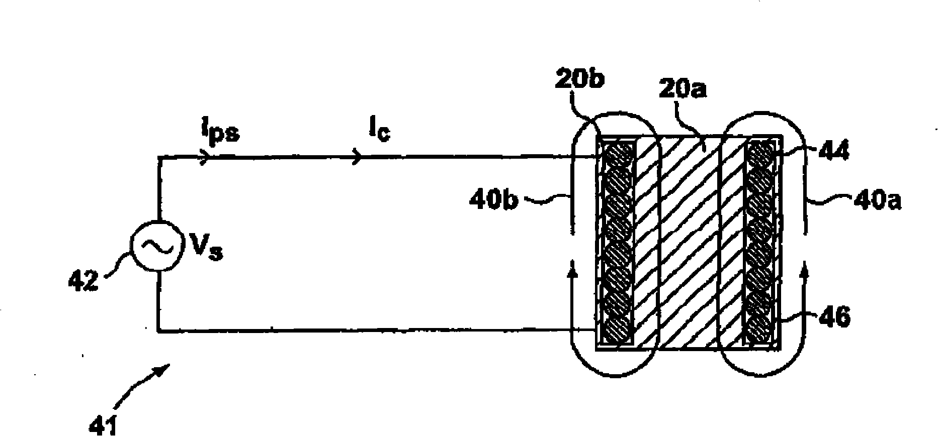
[0051] see image 3 , wherein a simplified schematic diagram of an exemplary embodiment 41 of the present invention is shown generally. A power source 42 supplies an alternating current to a heater coil 44 which is wound around and connected to objects 20a and 20b. In the preferred embodiment, without limitation, coil 44 is disposed within slot 46 formed between 22a and 22b, which forms a closed magnetic structure. When an alternating current is applied to the coil 44, magnetic field lines are generated, as indicated by arrows 40a, 40b. It should be noted that many flux lines are generated around the entire perimeter of the object, only two flux lines 40a, 40b are shown for simplicity. These flux lines generate eddy currents in the objects 20a, 20b, which generate heat according to the skin effect principle described above. In a preferred embodiment, the objects 20a, 20b may preferably be designed so that the maximum flux lines are generated, thereby generating as much heat...


PUM


Abstract

A method and apparatus for temperature control of an article is provided that utilizes both the resistive heat and inductive heat generation from a heater coil.

Description

technical field [0001] The present invention relates to a method and a device for controlling the temperature of an object, eg heating an object. More particularly, the present invention relates to a method and apparatus for improving heating performance by combining inductive heating and resistive heating produced by a heater. Background technique [0002] Referring to Figure 1, there is shown a typical resistive heater circuit 10 according to the prior art. The power supply 12 may provide a DC voltage or a typical line frequency AC voltage to a heater coil 14 that is wound in close proximity to an item 20 to be heated. In general, the heater coil 14 is formed of a resistive element, provided with an insulating layer 18 to avoid short circuits. It is also common to have the entire heater coil encased in a protective cover 16, thereby forming a modular heating unit. The prior art has many examples of methods of applying heat to a material and raising the temperature of th...

Claims


Application Information

Patent Timeline
Patent Type & Authority Applications(China)
IPC IPC(8): H05B6/02H05B6/14H05B11/00H05B6/06
CPCH05B2206/024H05B6/14
Inventor 詹姆斯·皮拉夫季奇斯特凡·冯布伦瓦列里·G·卡根
Owner HUSKY INJECTION MOLDING SYST LTD
Why Eureka
Try Eureka