Shell-pipe head exchanger by double helix flowing of fluid medium in or out of heat exchange tube

A shell-and-tube heat exchanger and fluid medium technology, applied in the direction of heat exchanger types, indirect heat exchangers, fixed tubular conduit assemblies, etc., can solve the problem of reducing the mass flow rate of the effective transverse tube bundle and reducing the heat transfer on the shell side Efficiency, shortening the life of the heat exchanger, etc., to achieve the effect of reducing scaling, reducing flow resistance and scaling, and enhancing disturbance

Inactive Publication Date: 2009-02-11
XI'AN PETROLEUM UNIVERSITY
View PDF0 Cites 15 Cited by
  • Summary
  • Abstract
  • Description
  • Claims
  • Application Information

AI Technical Summary

Problems solved by technology

[0003] There are many problems in the traditional bow-shaped baffles: ①The bow-shaped baffles cause the fluid to impact the shell wall vertically, resulting in a large pressure drop along the way; , reduces the heat transfer efficiency, and is easy to scale; ③ there is leakage between the baffle and the shell wall and between the heat exchange tube and the baffle, so that there is a large bypass flow on the shell side, and the side flow And the leakage flow reduces the mass flow rate of the effective cross-sweeping tube bundle, so the heat exchange efficiency of the shell side is reduced; ④The high-velocity fluid sweeping the heat-exchange tube bundle will induce the vibration of the heat-exchange tube and shorten the life of the heat exchanger

Method used


Image

  • Shell-pipe head exchanger by double helix flowing of fluid medium in or out of heat exchange tube
  • Shell-pipe head exchanger by double helix flowing of fluid medium in or out of heat exchange tube
  • Shell-pipe head exchanger by double helix flowing of fluid medium in or out of heat exchange tube

Examples


Embodiment 1

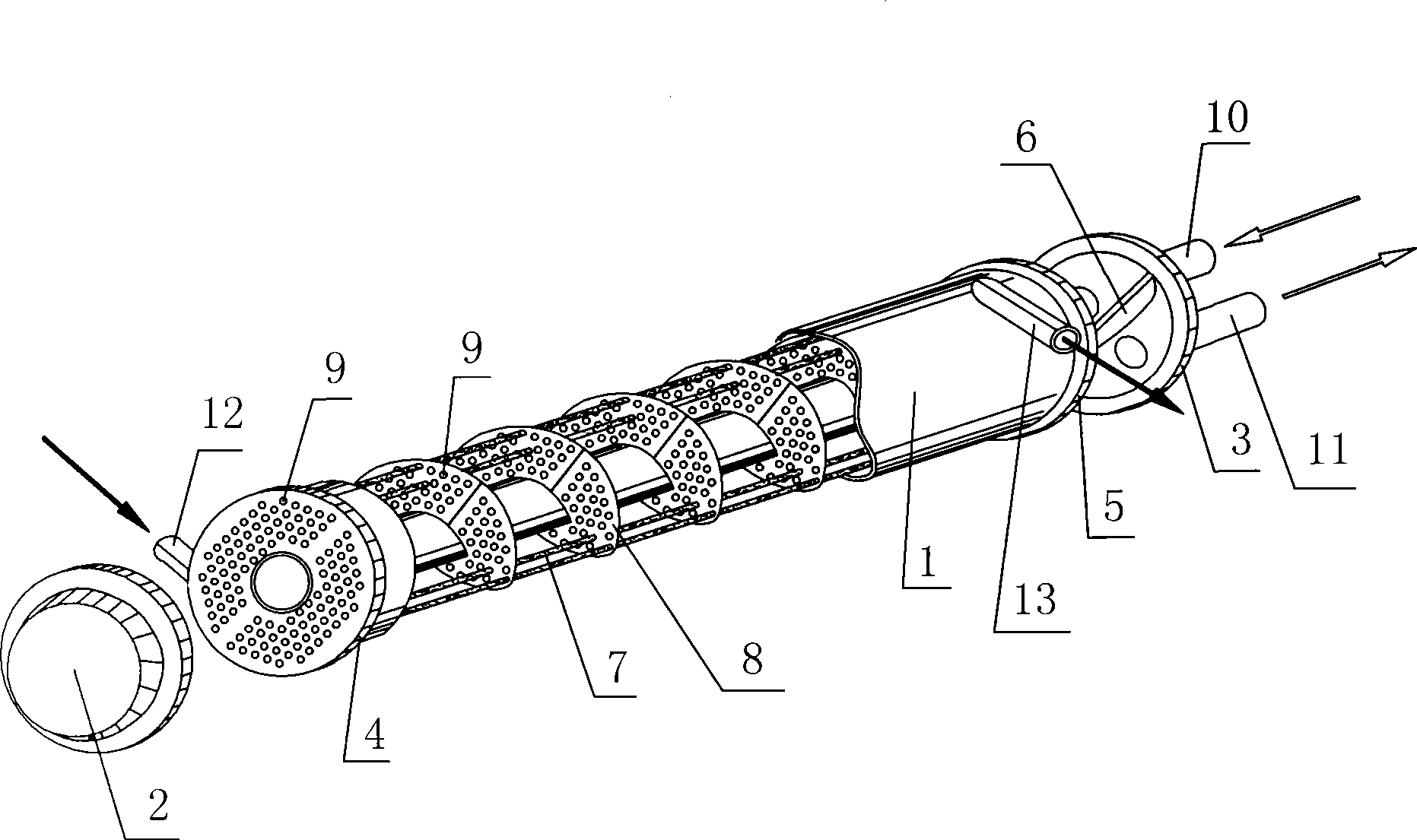
[0033] Such as figure 1 As shown, the present invention consists of a shell 1 sealed by two ends of the head, that is, the left head 2 and the right head 3, the shell side inlet 12 and the shell side outlet 13 arranged on the side wall of the shell 1, respectively located in the shell The first sealing plate 4 and the second sealing plate 5 at the two ends of the body 1, a group of tube-side inlets 10 and tube-side outlets 11 that are all arranged on the right head 3, baffles arranged inside the shell 1, and multiple parallel It consists of heat exchange tubes 7 installed between the first sealing plate 4 and the second sealing plate 5. Wherein, the shell side inlet 12 and the shell side outlet 13 are respectively located at two ends of the side wall of the housing 1 . The first sealing plate 4 and the second sealing plate 5 are correspondingly provided with a plurality of through holes 9 through which the heat exchange tubes 7 pass, and the outer walls of the heat exchange t...

Embodiment 2

[0041] Such as Figure 5 As shown, in this embodiment, the number of the tube pass inlet 10 and the tube pass outlet 11 is a group, and the tube pass inlet 10 and the tube pass outlet 11 are respectively located on the two heads at the left and right ends of the housing 1, specifically The tube side inlet 10 is located on the right head 3, the tube side outlet 11 is located on the left head 2, and there is no partition 6 between the sealing plate 2 5 and the right head 3, so that the longitudinal spiral flow channel It communicates with the tube-side inlet 10 and the tube-side outlet 11 to form a right-to-left helical one-way flow channel in the tube; the structure, connection relationship and function of the rest of the parts are the same as those in Embodiment 1. That is to say, the difference between this embodiment and Embodiment 1 is that: the tube-side inlet 10 and the tube-side outlet 11 are respectively located on the two heads, and the two form a unidirectional flow c...

Embodiment 3

[0044] Such as Figure 6 As shown, in this embodiment, two heat exchangers are connected in series, and the heat exchange fluid flows in from the shell-side inlet 12 of one of the heat exchangers, passes through the shell-side circulation channel formed by the spiral baffle 8, and flows The shell side outlet 13 of this heat exchanger flows out; at the same time, the shell side outlet 13 of this heat exchanger communicates with the shell side inlet 12 of another heat exchanger, so the heat exchange fluid flows from the shell side of another heat exchanger The inlet 12 flows in, also passes through the shell-side flow channel, and then flows out from the shell-side outlet 13, thus forming a back-and-forth double-shell-side flow channel. Specifically: the shell-side inlet 12 of the previous heat exchanger is located on the left side of the shell 1, and its shell-side outlet 13 is located on the right side of the shell 1; correspondingly, the shell-side inlet 12 of the next heat e...


PUM


Abstract

The invention discloses a shell and tube heat exchanger with fluid media duplex helicoidal flowing inside and outside a heat exchange tube, which consists of a shell sealed by an end enclosure, a shell side inlet and a shell side inlet which are arranged on the side wall of the shell, a close board A and a close board B which are arranged on two ends inside the shell, a tube side inlet and a tube side outlet which arranged on the end enclosure, a traverse baffle arranged inside the shell, and a plurality of heat exchange tubes which are arranged between the close board A and the close board B in parallel, wherein, heat exchange tube comprises an outer tube, a core tube and an inner fin which is circularly embedded between the outer tube and the core tube around the tube core; the traverse baffle is a helical traverse baffle communicating the shell side inlet and the shell side outlet; the traverse baffle, the shell side inlet and the shell side outlet form a vertical helical type shell side circulating channel; the inner fin is formed by bending a corrugated inner fin plate, and a vertical helical type inner fin tube between the outer tube and the core tube is formed; and the vertical helical type inner fin tube is communicated with the tube side inlet and the tube side outlet to form a circulating channel in tube. The invention has a simple and reasonable structure, and can decrease the occurring of low flow resistance and scale formation while strengthening the performance of heat transfer and heat exchange of shell side and tube side.

Description

technical field [0001] The invention relates to a shell-and-tube heat exchanger, in particular to a shell-and-tube heat exchanger with a double-helix flow of fluid medium inside and outside a heat exchange tube. Background technique [0002] In oil refining, chemical industry, environmental protection, energy, electric power and other industries, heat exchanger is an important unit equipment. Usually in the construction of chemical plants, heat exchanger accounts for about 10-20% of the total investment; especially in refineries In construction, heat exchangers account for about 35-40% of all process equipment investment. Among them, shell-and-tube heat exchangers account for 37% of the total heat exchanger market in the world. In a shell and tube heat exchanger, one fluid flows inside the tubes and the other fluid flows on the shell side and exchanges heat through the tubes. At the same time, baffles are arranged on the shell side, and the baffles provide support for the ...

Claims


Application Information

Patent Timeline
Patent Type & Authority Applications(China)
IPC IPC(8): F28D7/10F28D7/02
Inventor 吴峰
Owner XI'AN PETROLEUM UNIVERSITY
Why Eureka
Try Eureka