
Manufacturing method for combined high-speed electro-magnet iron core

A high-speed electromagnet and combined iron core technology, which is applied in the manufacture of inductors/transformers/magnets, magnetic cores/yokes, circuits, etc. problem, to achieve the effect of simple structure, reduced volume and easy processing

Inactive Publication Date: 2009-02-11
易军 +1
View PDF2 Cites 9 Cited by
  • Summary
  • Abstract
  • Description
  • Claims
  • Application Information

AI Technical Summary

Problems solved by technology

[0003] Chinese Patent Application No. 200410081417.1 Authorization No. CN100385106C discloses a miniaturized high-speed electromagnet. Since the iron core of the electromagnet is integrally processed with electrical pure iron or silicon steel material, the eddy current of the electromagnet is large and the heat generation is large, which cannot meet the needs of diesel motors. The fuel injection system has a fast response to high-speed electromagnets, and the requirements for sufficient electromagnetic force are difficult for practical application.

Method used


Image

  • Manufacturing method for combined high-speed electro-magnet iron core
  • Manufacturing method for combined high-speed electro-magnet iron core
  • Manufacturing method for combined high-speed electro-magnet iron core

Examples


Embodiment 1

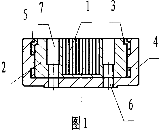
[0046] The present embodiment provides a kind of manufacturing method of combined high-speed electromagnet iron core, and the combined high-speed electromagnet iron core to be processed is a kind of circular shape iron core, as shown in Figure 1, by iron core assembly 1, iron The core seat 2 and the non-magnetic metal outer jacket 4 are composed, and the processing steps are characterized as follows:

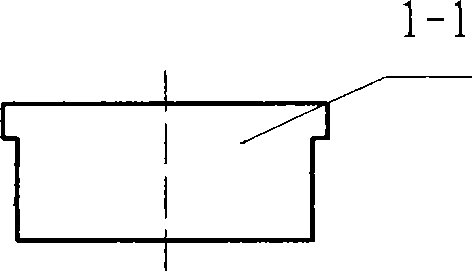
[0047] One, such as figure 2 As shown in the figure, the lamination sheet 1-1 of the iron core assembly is formed by blanking by cold stamping, and then a number of formed iron sheet sheets 1-1 are superimposed into the iron core assembly 1 by lamination, which is made of oriented silicon steel sheet Formed iron chips, the orientation of the grain-oriented silicon steel sheet is perpendicular to the working surface of the iron core, see image 3 and Figure 4 ;

[0048] 2. Process the overall soft magnetic material into a circular iron core seat 2 by mechanical processing, an...

Embodiment 2

[0060] The present embodiment provides a kind of manufacturing method of combined high-speed electromagnet iron core, and the combined high-speed electromagnet iron core to be processed is a kind of circular shape iron core, as shown in Figure 1, by iron core assembly 1, iron The core seat 2 and the non-magnetic metal outer jacket 4 are composed, and the processing steps are characterized as follows:

[0061] One, such as figure 2 As shown, the lamination sheet 1-1 of the iron core assembly is blanked and formed by cold punching, and then a number of formed iron sheet sheets 1-1 are superimposed into the iron core assembly 1 by lamination, see image 3 and Figure 4 ;

[0062] 2. Process the overall soft magnetic material into a circular iron core seat 2 by mechanical processing, and process a through groove 2-1 in the horizontal direction of the middle part of the circular iron core seat 2, and process a 0.5mm× 45° circular chamfer 2-2, such as Figure 5 shown;

[0063] ...

Embodiment 3

[0074] The present embodiment provides a method for manufacturing a combined high-speed electromagnet core. The combined high-speed electromagnet core to be processed is a circular iron core. As shown in Figure 17, the iron core assembly 1, iron core The core seat 2 and the non-magnetic metal outer jacket 4 are composed, and the processing steps are characterized as follows:

[0075] One, such as figure 2 As shown, the lamination sheet 1-1 of the iron core assembly is blanked and formed by cold punching, and then a number of formed iron sheet sheets 1-1 are superimposed into the iron core assembly 1 by lamination, see image 3 and Figure 4 ;

[0076] 2. Process the overall soft magnetic material into a circular iron core seat 2 by mechanical processing, and process a through groove 2-1 in the horizontal direction of the middle part of the circular iron core seat 2, and process a 0.4mm× 45° circular chamfer 2-2, such as Figure 5 shown;

[0077] 3. Embed the iron core ass...


PUM


Abstract

The invention relates to a production method of a combined high-speed electromagnet iron core. The iron core comprises an iron core assembly, an iron core base and a non-magnetic conducting metal housing. The production method comprises the steps of preparing a silicon steel sheet into single sheet formed iron core sheets; laminating to obtain the iron core assembly; integrally embedding into the groove of the iron core base made from a soft magnetic material; removing the part of the iron core assembly over the groove to obtain a combined iron core body; processing the end of the combined iron core body to be a ring-shaped step; loading into the non-magnetic conducting metal housing; filling epoxy glue into the reserved space therebetween; drying and solidifying; processing a ring-shaped groove on the end surface of the solidified combined iron core body, which is positioned above the iron core body and between the outer side of the iron core assembly and the non-magnetic conducting metal housing and is concentric with the round combined iron core body; and forming two coil leading holes in the groove, which pass through the bottom of the iron core base and the bottom of the non-magnetic conducting metal housing. The method combines the silicon steel sheet with the integral soft magnetic material, and carries out mechanical processing after the combination.

Description

technical field [0001] The invention relates to a manufacturing method of an electromagnet iron core, in particular to a manufacturing method of a combined high-speed electromagnet iron core used in electronically controlled fuel injection systems of various diesel engines. technical background [0002] The high-speed electromagnet is the key control executive element in the electronically controlled fuel injection system of the diesel engine. In order to achieve high-precision control of the fuel injection quantity in the electronically controlled fuel injection system of the diesel engine, the high-speed electromagnet used is required to have small eddy current and fast response speed. , low heat generation, and can generate a large enough electromagnetic force. At present, the electromagnet of diesel engine electronically controlled fuel injection system widely adopts E-type laminated iron core. The electronically controlled unit pump produced by BOSCH company and the ele...

Claims


Application Information

Patent Timeline
IPC IPC(8): H01F41/02H01F3/02
Inventor 李志强易军
Owner 易军
Learn More