Kinetic energy storage apparatus

A kinetic energy and power technology, which is applied in the field of energy-saving mechanical devices, can solve the problems of large weight increase, low manufacturing and installation costs, and difficult promotion and application.

Inactive Publication Date: 2009-03-04
陆中源
View PDF1 Cites 5 Cited by
  • Summary
  • Abstract
  • Description
  • Claims
  • Application Information

AI Technical Summary

Problems solved by technology

Compared with the above two kinds of hybrid electric buses, the "braking energy storage flywheel device" installed on the bus has the same or better energy-saving and pollution-reducing effects, can subsidize braking and lower cost, and basically does not need to change gears when starting. However, there are still major shortcomings such as heavy weight increase, low manufacturing and installation costs, and difficulty in popularization and application, which need to be improved.

Method used


Image

  • Kinetic energy storage apparatus
  • Kinetic energy storage apparatus
  • Kinetic energy storage apparatus

Examples


Embodiment Construction

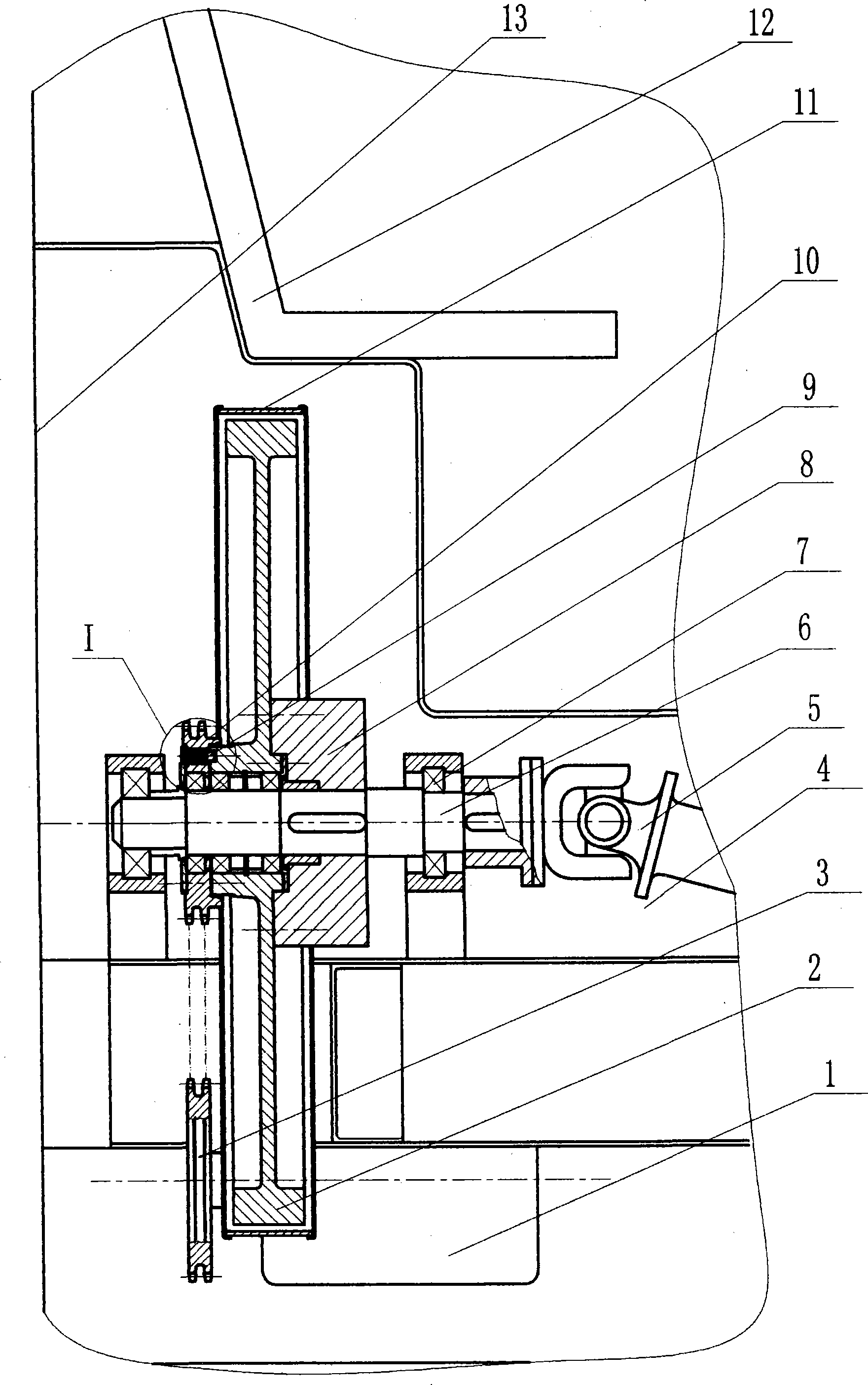
[0005] Depend on figure 1 , 6 It can be seen that these three embodiments all have a flywheel (2) and its power inlet and outlet shaft (6), and the flywheel (2) is connected with the power inlet and outlet shaft (6) through a friction clutch (8). It is characterized in that: the flywheel (2) Overrunning clutch (10) and electric motor (1) are arranged beside, and flywheel (2) is connected with electric motor (1) transmission through overrunning clutch (10).

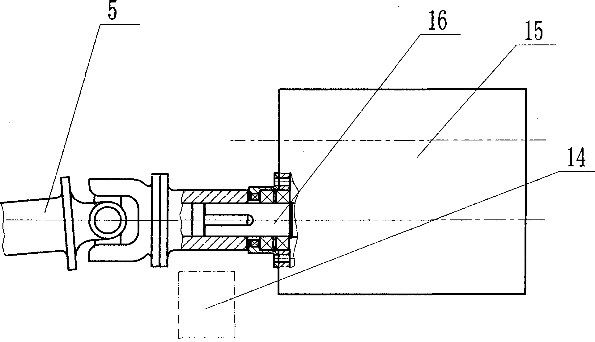
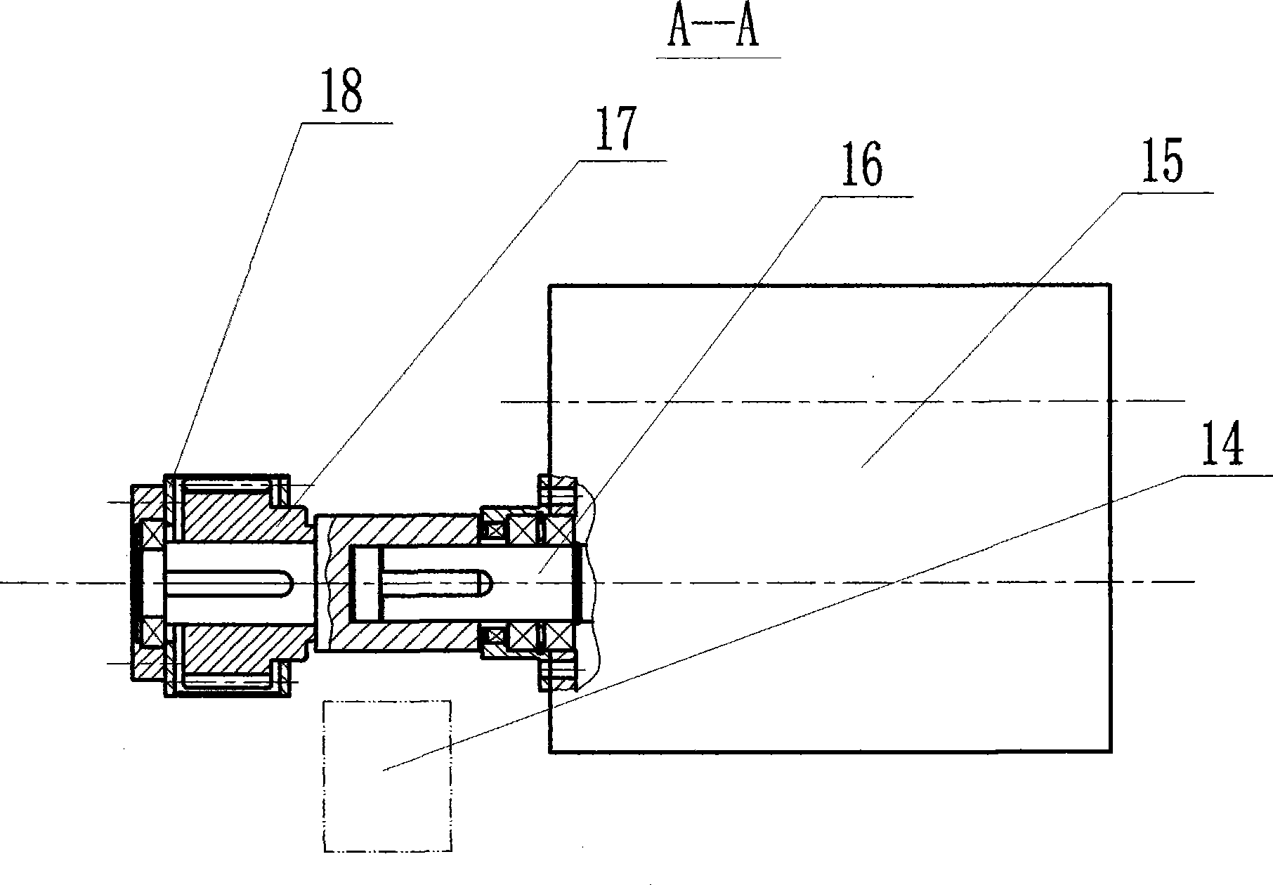
[0006] Further, by figure 1 , 2 , 3, 4, 6, it can be seen that the flywheel (2), the power input and output shaft (6) and the motor (1) are all installed on the chassis frame (4) of the motor vehicle, and the power input and output shaft (6) is driven by the motor vehicle transmission (15) Connect, electric motor (1) provides electric power by the storage battery on the car. In the armature circuit of the motor (1), control devices such as an overcurrent relay and a time relay are connected in series. Certainly, what ...


PUM


Abstract

The invention discloses a machine mainly used for storing and releasing kinetic energy when a bus is braked and started. The machine includes a flywheel (2) and a power input/output shaft (6); the flywheel (2) is in transmission linkage with the power input/output shaft (6) through a friction clutch (8); an overrunning clutch (10) and an electric motor (1) are arranged beside the flywheel (2); and the flywheel (2) is in transmission linkage with the electric motor (1) through the overrunning clutch (10). When the machine is used by a vehicle, such as the bus, etc., the driving kinetic energy of the vehicle can drive the flywheel (2) to turn faster through braking; after braking, the electric motor (1) further accelerates the flywheel (2) to a high speed by the overrunning clutch (10) when the friction clutch (8) is separated for stopping the vehicle; and the stored kinetic energy and electric energy can be passed from the flywheel (2) to the vehicle for starting the vehicle. Compared with other similar machines, the machine has the advantages that the vehicle can use cheap and renewable electrical energy when the vehicle is started; the effects of saving oil and reducing pollutant are obvious; and the machine is simple, reliable, and low in cost. Therefore, the machine is easy to popularize and apply.

Description

technical field [0001] The invention relates to a power mechanical device, especially an energy-saving mechanical device used for kinetic energy storage and storage during braking and starting of motor vehicles such as buses. Background technique [0002] For a long time, how to recover the kinetic energy of power equipment (especially motor vehicles such as buses) efficiently and at low cost has been a major energy-saving problem in the machinery industry. Two kinds of so-called " hybrid electric buses " have occurred in recent years, and a kind of has installed braking storage energy hydraulic system additionally, and another kind is to have installed braking storage energy electric system additionally. When braking to decelerate or going downhill, the driving kinetic energy or potential energy of the two vehicles is converted into hydraulic energy or electric energy and stored in the hydraulic accumulator or battery; when the vehicle starts or accelerates, the energy stor...

Claims


Application Information

Patent Timeline
Patent Type & Authority Applications(China)
IPC IPC(8): B60T1/10B60K6/10
CPCY02T10/6204Y02T10/62
Inventor 陆中源
Owner 陆中源
Why Eureka
Try Eureka