Apparatus for collecting compressed air by ambient pressure

A technology of compressing air and external pressure, which is applied to equipment loaded into pressure vessels, gas/liquid distribution and storage, liquid variable capacity machinery, etc. It can solve the problems of long production cycle, failure to save energy, and limited use range, etc. problem, to achieve the effect of low input cost, high conversion efficiency, and easy promotion

Inactive Publication Date: 2009-03-04
朱仕亮
View PDF0 Cites 36 Cited by
  • Summary
  • Abstract
  • Description
  • Claims
  • Application Information

AI Technical Summary

Problems solved by technology

At present, the acquisition and development of the above-mentioned energies requires a lot of investment, the energy conversion rate is low, the requirements for the basic supporting environment are high, the output cycle is long, and it is difficult to promote.
In addition, compressed air is used as an energ

Method used


Image

  • Apparatus for collecting compressed air by ambient pressure
  • Apparatus for collecting compressed air by ambient pressure
  • Apparatus for collecting compressed air by ambient pressure

Examples


Embodiment 1

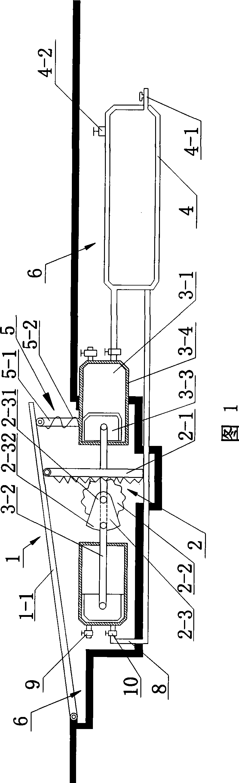
[0017] Implementation example 1, please refer to Fig. 1, a device that utilizes external pressure to collect compressed air, including a pressurizing device 1, a driving device 2, a cylinder 3-1, a pressure accumulator 4 and a reset device 5, the pressurizing device 1 Installed on the upper surface of the foundation pit 6, the foundation pit 6 can set up places such as the road surface of the gas station, the dock container loading and unloading, the above-mentioned device is installed in the foundation pit 6 of the road surface 7 in this implementation example, and the gravity of the external weight can be collected. The pressure generated by the pressure plate 1-1 of the pressurizing device 1, the pressurizing device 1 mainly includes a pressure plate 1-1 forming an angle with the horizontal plane, one end of the pressure plate 1-1 is hinged to the foundation pit 6, The other end is a free end, and the pressure plate 1-1 can make a reciprocating arc movement around the connec...

Embodiment 2

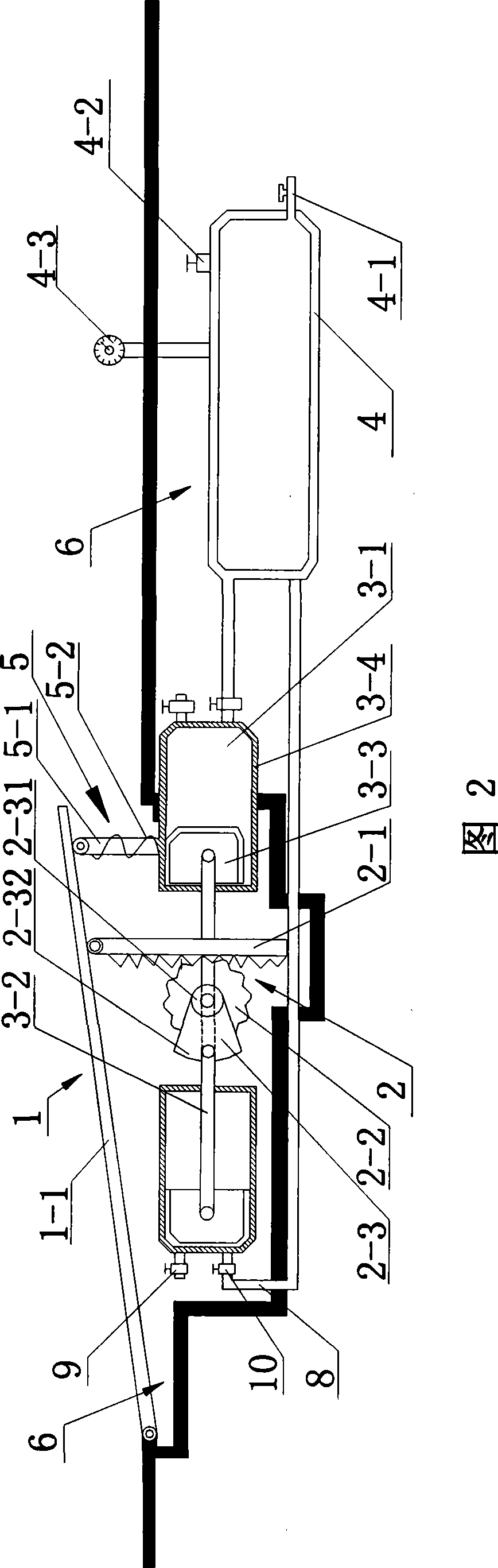
[0018] Implementation example 2, please refer to Fig. 2, in order to obtain the pressure value of pressure accumulator 4, also be provided with the pressure gauge 4-3 that can read pressure value on pressure accumulator 4, can observe the pressure in pressure accumulator 4 at any time Value, other structures are identical with embodiment 1.

[0019] The state of use of the present invention:

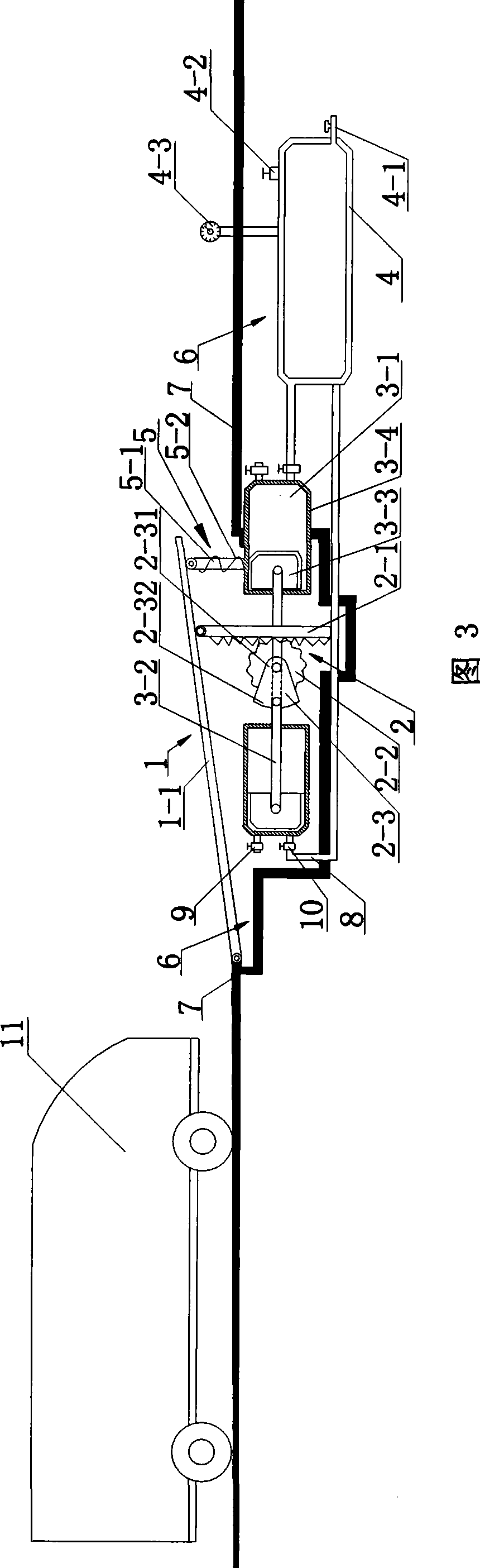
[0020] Please refer to Fig. 3, the foundation pit in the above-mentioned structure is arranged on the bigger place of motor vehicle flow such as gas station, toll station, when the motor vehicle 11 of running travels to pressure plate 1-1, a pressure plate 1-1 is produced. Downward pressure, the pressure plate 1-1 drives the driving device 2 to make the cylinder 3-1 do work, thus generating compressed air, which is collected in the pressure accumulator 4, and the compressed air in the pressure accumulator 4 reaches a certain pressure value , provide users with high-pressure gas.

[002...


PUM


Abstract

The present invention relates to a device capable of utilizing the outside pressure to collect compressed air. The device comprises a pressure unit, a driver, an air cylinder, a pressure storage unit and a resetter; wherein, the pressure unit, which is mounted on the upper surface of a foundation pit arranged on a road surface, comprises a pressure plate, one end of which is hinged with the foundation pit and the other end of which is a free end; the driver, which is mounted on the lower surface of the pressure plate, comprises a rack, which is movably connected with the pressure plate and engaged with a gear; a crankshaft is mounted on the gear; a piston rod of the air cylinder is hinged with the crankshaft; the air cylinder is communicated with the pressure storage unit, which is provided with a pressure meter; and the resetter is mounted on the lower surface of the free end of the pressure plate. The device does not generate any pollution and can recover the energy wasted by a heavy object to the max, thus achieving the purpose of turning the waste into a valuable. Moreover, the device also has the advantages of simple structure, reasonable design, little investment and cost, high conversion efficiency and easy promotion.

Description

technical field [0001] The invention belongs to the field of renewable energy collection, in particular to a device for collecting compressed air by using external pressure. Background technique [0002] As we all know, people have been using various energy sources for development for a long time, reducing the use of oil and natural gas as much as possible. In order to achieve the purpose of saving energy, some areas are also trying to develop clean energy and new energy, such as: wind energy, solar energy, hydrogen energy and plant energy. At present, the acquisition and development of the above-mentioned energies requires a lot of investment, the energy conversion rate is low, the basic supporting environment requirements are high, the output cycle is long, and it is difficult to promote. In addition, compressed air is used as an energy source. Currently, compressed air is generally obtained through an air compressor, and the compressed air machine also consumes external ...

Claims


Application Information

Patent Timeline
IPC IPC(8): F04B35/00F17C5/00
Inventor 朱仕亮
Owner 朱仕亮
Why Eureka
Try Eureka