Blind equalizing method in satellite demodulator

A technology of satellite demodulator and blind equalization, which is applied to the shaping network and baseband system components in the transmitter/receiver, and can solve the problem of wasting time and resources of transmission

Active Publication Date: 2009-03-11
深圳市统先科技股份有限公司
View PDF0 Cites 10 Cited by
  • Summary
  • Abstract
  • Description
  • Claims
  • Application Information

AI Technical Summary

Problems solved by technology

The traditional approach is to waste a part of the tran

Method used


Image

  • Blind equalizing method in satellite demodulator
  • Blind equalizing method in satellite demodulator
  • Blind equalizing method in satellite demodulator

Examples


Embodiment Construction

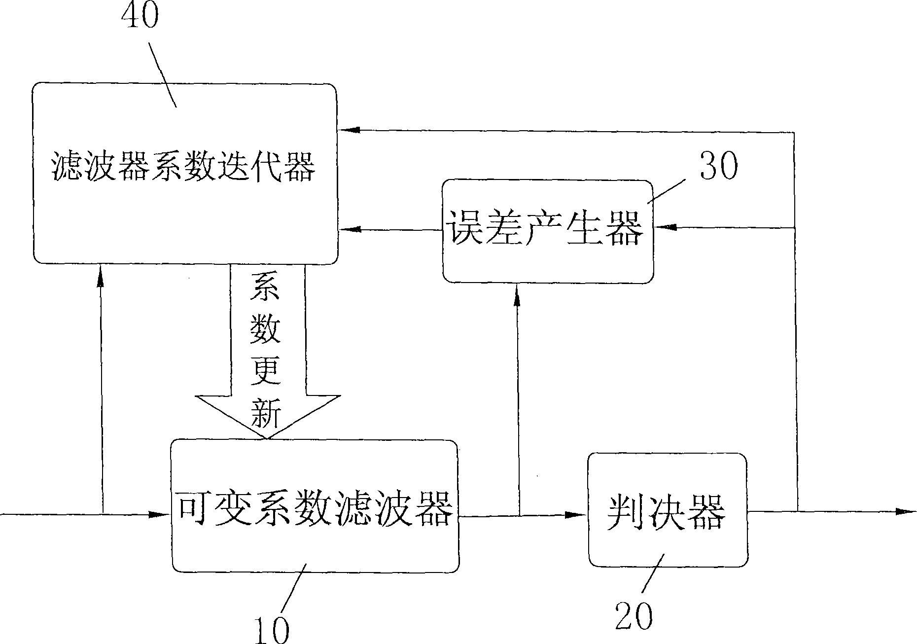
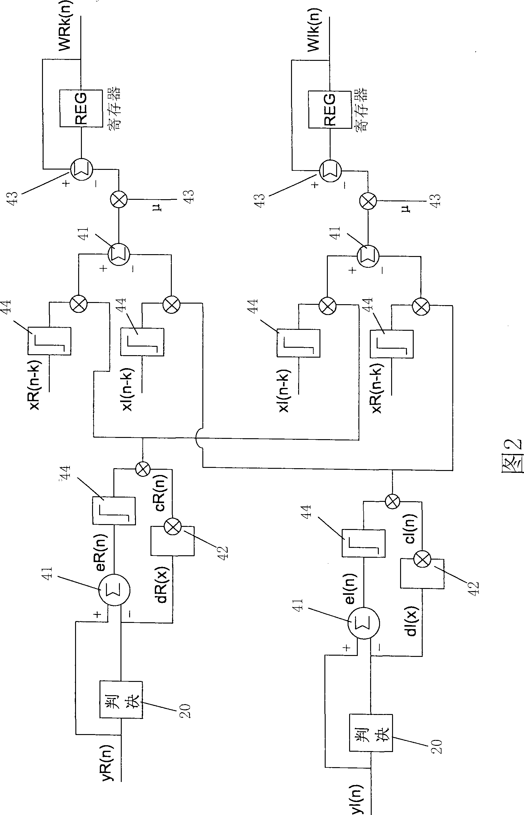
[0021] Such as figure 1 As shown in -2, the blind equalizer structure adopted by the method of the present invention is mainly composed of a variable coefficient filter 10, a decision device 20, an error generator 30, and a filter coefficient iterator 40, and the blind equalizer is restored by the following steps Send serial signal:

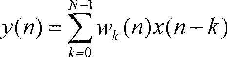
[0022] 1) The input complex sequence signal x(n)=xR(n)+jxI(n) enters the variable coefficient filter 10 one way, and the other way enters in the filter coefficient iterator 40; The digital circuit calculates according to the following convolution formula to obtain the output complex sequence signal y(n)=yR(n)+jyI(n):

[0023] y ( n ) = Σ k = 0 N - 1 w k ( n ) ...


PUM


Abstract

The invention relates to a blind equalization method in satellite demodulator, which is an improvement on the existing minimum mean-square, the algorithm of the invention is as follows: wRk(n+1) equals to wR)k(n) minus eta (cR(n) multiplied by sign(eR(n))sign(xR(n-k)) plus cI(n) multiplied by sign(eI(n))sign(xI(n-k))), wIk(n +1) equals to wIk(n) plus eta (cR(n) multiplied by sign(eR(n))sign(xI(n-k))-cI(n) multiplied by sign(eI(n))sign(xR(n-k)) ), wherein cR(n)equals to (dR(n))<2>, cI(n) equals to (dI(n))<2>, eta is a stepping constant, the function sign is a symbol-fetching function; when the blind equalization method of the invention is adopted, the hardware scale of the existing blind equalization devices can be simplified, the multiplier can be dispensed, the computation volume is reduced, the computing capability is greatly improved, and the sequence sending can be correctly restored in real time for signal inputting.

Description

technical field [0001] The invention relates to the field of satellite communication, satellite remote sensing, and satellite broadcast ground digital receiving systems, and specifically designs a blind equalization method suitable for high-speed satellite digital demodulators. Background technique [0002] In wireless digital communication systems, the inherent bandwidth limitation of the channel tends to increase the distortion of the received signal, for example, the bandwidth-limited channel tends to cause the spread of the transmitted pulse. If the width of the spread pulse exceeds the duration of one symbol, overlapping of adjacent pulses will occur, degrading receiver performance. This phenomenon is called intersymbol interference (ISI). Channel distortion and intersymbol interference (ISI) caused by distortion is a major factor affecting communication quality, which needs effective channel equalization technology to eliminate. The traditional approach is to waste a ...

Claims


Application Information

Patent Timeline
IPC IPC(8): H04L25/03
Inventor 李黎明
Owner 深圳市统先科技股份有限公司
Why Eureka
Try Eureka