An implant drill

A technology of main body and components, applied in dental implants, medical science, dentistry, etc., can solve problems such as maxillary lining membrane damage

Inactive Publication Date: 2009-03-11
宋泳玩
View PDF0 Cites 15 Cited by
  • Summary
  • Abstract
  • Description
  • Claims
  • Application Information

AI Technical Summary

Problems solved by technology

However, when the process of drilling by rotating the drill bit ends, since nothing is prepared to prevent the drill bit from coming into contact with the maxillary lining membrane, the maxillary lining membrane can be damaged by being torn or rolled up by the drill tip

Method used


Image

  • An implant drill
  • An implant drill
  • An implant drill

Examples


Embodiment Construction

[0053] The present invention will now be described more fully with reference to the accompanying drawings showing preferred exemplary embodiments of the invention.

[0054] image 3 to 8 are used to explain the implant drill A for maxillary sinus elevation according to the exemplary embodiment of the present invention.

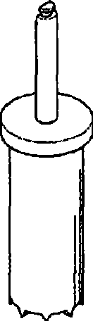
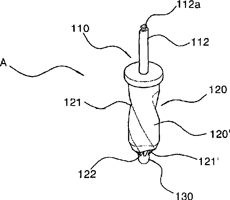
[0055] Such as image 3 As shown, the implant drill A includes a connector 110 , a drill bit 120 and a protruding part 130 .

[0056] The connecting member 110 is in the shape of a disc with a diameter ranging from 4 to 5 mm, and includes a fixing edge 111 , a handle 112 a and a central shaft 112 . The fixing edge 111 is formed under the lower surface of the connector 110 and has a circular shape with an outer diameter smaller than that of the connector 110 . A central shaft 112 with a shank 112a is placed at the center on the upper surface of the connector 110 .

[0057] The drill bit 120 is cylindrical and has a diameter of about 3 mm, which is slightly ...


PUM


Abstract

There is provided an implant drill for maxillary sinus lifting, which is capable of easily and simply boring the maxillary bone, without damaging the lining membrane of the maxillary sinus, to easily operate the maxillary sinus lifting and to expand a boring part of the maxillary bone for implant placement. The implant drill for maxillary sinus lifting, which includes a central shaft with a shank in a body to be mounted onto a general dental hand piece, comprises a protrusion member elastically positioned in the body so as to move forward and backward or a lifting member being free from the rotation of the body.

Description

technical field [0001] The present invention relates to dental implant drills, and more particularly, to implant drills for maxillary sinus lifts, which allow easy and simple drilling of holes in the maxilla without damaging the lining membrane of the maxillary sinuses , which allows easy sinus lift and enlargement of the foramen in the maxilla for implant placement. Background technique [0002] Implant surgery for implanting dentures is rapidly gaining in popularity. [0003] However, the oral structure of a considerable number of patients is difficult to implement implant surgery. For this reason, some dentists are reluctant to perform implant surgery in such patients. [0004] In particular, implantation is very difficult when the remaining bone in the posterior region where the maxillary sinus is located is insufficient. In this case, after a space is obtained by lifting the lining of the maxillary sinus, bone is grafted into the resulting space, and then the implant...

Claims


Application Information

Patent Timeline
Patent Type & Authority Applications(China)
IPC IPC(8): A61C3/02
CPCA61C8/0092A61B17/1622A61B17/1626A61B17/1688A61B90/03A61B2090/033A61C3/02
Inventor 宋泳玩
Owner 宋泳玩
Why Eureka
Try Eureka