Check patentability & draft patents in minutes with Patsnap Eureka AI!

Method for connecting return conductors of power supply DC coaxial cables and connection portion between power supply dc coaxial cables

A technology of loop conductors and coaxial cables, which is applied in the direction of cable joints, manufacturing coaxial cables, and equipment for connecting/terminating cables, etc., which can solve the problems of insufficient electromagnetic shielding characteristics, enhanced thermal damage of the main insulation layer, and welding operation time Shorten the connection work time, improve the connection usability, and reduce the heat generation.

Inactive Publication Date: 2009-03-11
FURUKAWA ELECTRIC CO LTD +2
View PDF1 Cites 2 Cited by
  • Summary
  • Abstract
  • Description
  • Claims
  • Application Information

AI Technical Summary

Problems solved by technology

[0008] For the return conductor connection of each DC coaxial cable with the same return conductor composition (wire diameter and wire number), although the existing return conductor can be used The method of butt welding the core wires one by one, but the conventional connection method has the following problems: if the number of core wires of the loop conductor is large, the number of welding times will increase, and the welding work time will become longer
[0010] In addition, in the case of soldering the return conductor core wire on the outer semiconductive layer of the cable core or the connection part, the following problems arise: the heat generated during soldering Thermal damage to the outer semiconductive layer and main insulation of the cable, and the outer semiconductive layer and reinforced main insulation of the connection
[0017] If the distance between the core wires of the loop conductor is widened, the following problems will occur: the electromagnetic shielding property is not sufficient
In addition, it can be considered that once a gap is formed between the loop conductor core wires, the flow of current through the adjacent loop conductor core wires almost disappears. Therefore, at the cable connection part, when the current flowing in each loop conductor core wire When the value is unbalanced, the current may be concentrated in some loop conductor core wires, resulting in abnormal heating

Method used


Image

  • Method for connecting return conductors of power supply DC coaxial cables and connection portion between power supply dc coaxial cables
  • Method for connecting return conductors of power supply DC coaxial cables and connection portion between power supply dc coaxial cables
  • Method for connecting return conductors of power supply DC coaxial cables and connection portion between power supply dc coaxial cables

Examples


Embodiment approach 1

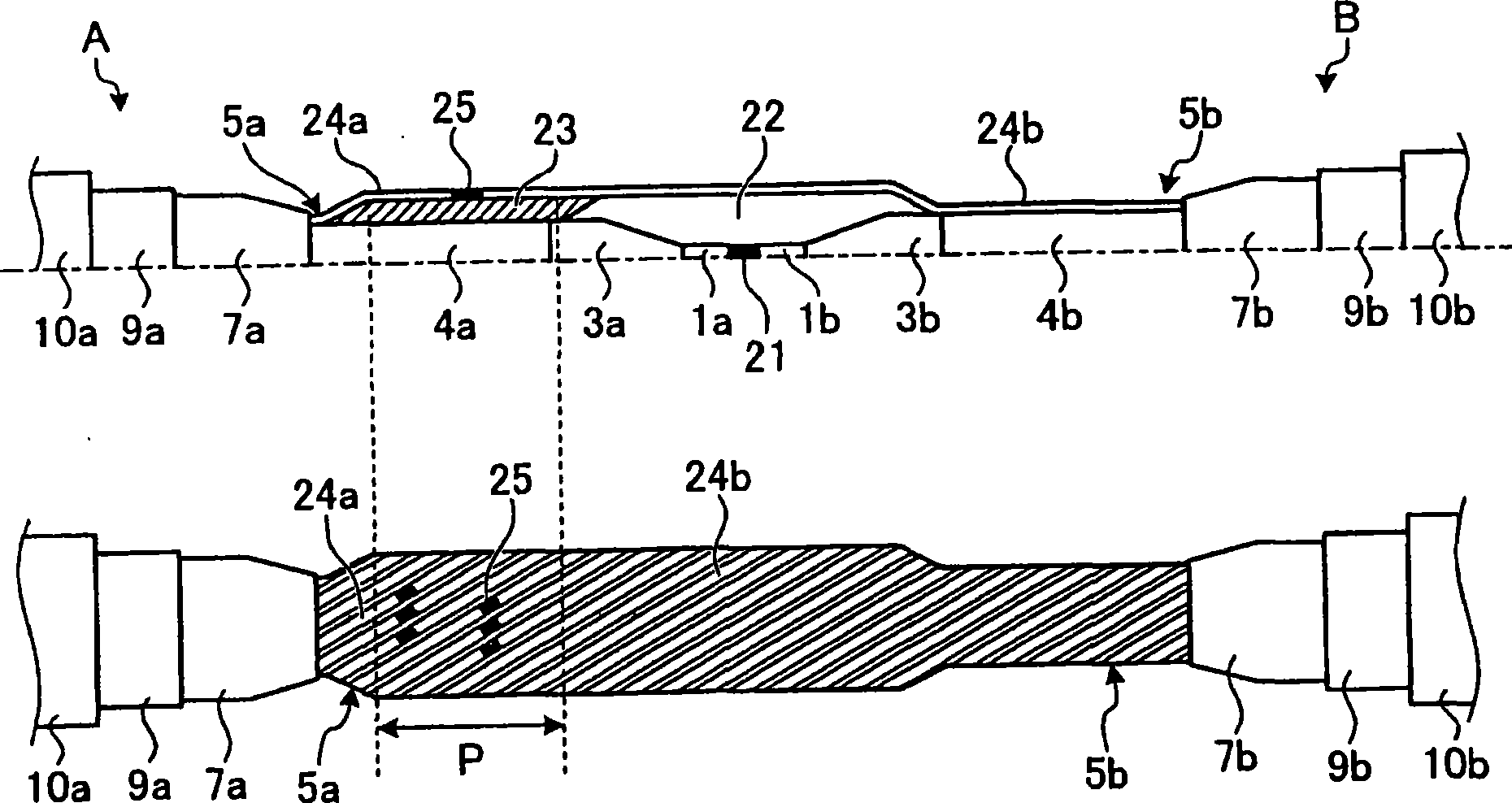
[0065] figure 1 It is a longitudinal sectional view and a partial sectional view of main parts of a DC coaxial cable connection portion for electric power using the loop conductor connection method according to Embodiment 1 of the present invention. The DC coaxial cables A and B to be connected respectively have Figure 17 With the same structure as shown, the anticorrosion layer 10a, 10b, lead cladding 9a, 9b, loop insulator 7a, 7b, outer semiconducting layer 4a, 4b, main insulating layer 3a, 3b are peeled off layer by layer, so that the leading end is exposed. Body 1a, 1b, so that the main conductor 1a, 1b is welded. Reference numeral 21 is a welded portion of the main conductors 1a, 1b. The main conductors 1a, 1b and their solder connections 21 are insulated by a reinforced main insulation layer 22 formed across the main insulation layers 3a, 3b of the two cables. In addition, a buffer layer 23 is provided on the outer semiconductive layer 4a of a square DC coaxial cable...

Embodiment approach 2

[0069] Although the above-mentioned first embodiment is the case where the number and wire diameter of the return conductor core wires of the DC coaxial cable to be connected are the same, but for the case where the number and wire diameter of the return conductor core wires are different, the present invention also Connection of loop conductors is possible. image 3It is an explanatory diagram of a connection method when the number and wire diameter of the loop conductor core wires according to Embodiment 2 of the present invention are different. In Embodiment 2, in Embodiment 1, the DC coaxial cable A is replaced with a DC coaxial cable C having a different number and diameter of loop conductor core wires. In addition, since the other configurations are the same as in Embodiment 1, the same parts are given the same reference numerals. In Embodiment 2, the number of core wires constituting each return conductor core wire bundle 24b, 24c is adjusted so that the number of retu...

Embodiment approach 3

[0071] Figure 5 It is an explanatory drawing explaining the loop conductor connection method of Embodiment 3 of this invention. In this connection method, although the loop conductor core wires 12b, 12c of both DC coaxial cables B, C are arranged adjacent to each other to form the loop conductor core wire bundles 24b, 24c, it is different from the above-mentioned Embodiment 2 is the same, but each return conductor core wire bundle 24b, 24c is connected by welding the front ends of both return conductor core wire bundles 24b, 24c to separately prepared relay wire bundles 26, respectively.

[0072] In the method for connecting the loop conductors described above, compared with the case of directly welding the loop conductor core strands of the DC coaxial cables B and C, it is easier to adjust the welding position of the front end of the loop conductor core strands. In addition, when the configuration (wire diameter and number of wires) of the loop conductor core wire harness t...


PUM

PropertyMeasurementUnit
Winding thicknessaaaaaaaaaa
Thicknessaaaaaaaaaa

Abstract

A power supply DC coaxial cable has a main conductor at the center, a main insulating layer outside the main conductor, and a return conductor comprising a large number of return conductor wires coaxially twisted outside the main insulating layer. In a method for connecting the return conductors at the connection portion between the power supply DC coaxial cables, a plurality of return conductor wires of the DC coaxial cables on both sides are adjacently arranged to form each return conductor wire bundle, and the ends of the return conductor wire bundles on both sides are faced to each other and then welded together. This enables the time required for welding the return conductor wires to be reduced and provides a method for connecting the return conductors of DC coaxial cables, which is also applicable to the return conductor connection between DC coaxial cables each having a different number of return conductor wires.

Description

technical field [0001] The present invention relates to a connection method of a return conductor on a connection portion between power coaxial cables having a return conductor coaxial with a central main conductor, and a connection portion of a DC coaxial cable for power. Background technique [0002] Figure 17 An example of a DC coaxial cable for electric power is shown. The center of the DC coaxial cable A has a main conductor 1, and its outer side is sequentially coaxially provided with an inner semiconducting layer 2, a main insulating layer 3, an outer semiconducting layer 4, a loop conductor 5, a loop inner semiconducting layer 6, and loop insulation Layer 7, circuit outer semiconductive layer 8, lead cladding 9 and anti-corrosion layer 10 (referring to patent document 1 figure 1 ). [0003] The main conductor 1 to the outer semiconducting layer 4 constitute a cable core 11 . The return conductor 5 is formed by concentrically stranding a plurality of return-condu...

Claims


Application Information

Patent Timeline
IPC IPC(8): H02G15/08H02G1/14H01B13/016
Inventor 水野健彦川上真一
Owner FURUKAWA ELECTRIC CO LTD
Features
  • R&D
  • Intellectual Property
  • Life Sciences
  • Materials
  • Tech Scout
  • Unparalleled Data Quality
  • Higher Quality Content
  • 60% Fewer Hallucinations
Learn More