Cold roller steel strip blowing and drawing type dust catching device

A technology for cold-rolled strip steel and dust is applied in the field of dust source control devices, which can solve the problems of unsatisfactory dust control effect of pickling unit and levelling unit, increase power consumption, affect production process, etc., and achieve good dust source control effect. , the effect of saving power and simple structure

Inactive Publication Date: 2009-03-18
WUHAN UNIV OF SCI & TECH
View PDF0 Cites 9 Cited by
  • Summary
  • Abstract
  • Description
  • Claims
  • Application Information

AI Technical Summary

Problems solved by technology

[0005] However, the dust control effect of the pickling unit and skin pass unit in the cold rolling mill is not satisfactory at present, because the loose iron oxide scale on the surface of the strip will fall off due to vibration during the high-speed operation of the strip, that is, it is not only in the straightening A large amount of dust is generated at the straightening machine, welding machine and stretch leveler, but there are different degrees of dust on the entire strip, and the dust

Method used


Image

  • Cold roller steel strip blowing and drawing type dust catching device
  • Cold roller steel strip blowing and drawing type dust catching device
  • Cold roller steel strip blowing and drawing type dust catching device

Examples


Embodiment 1

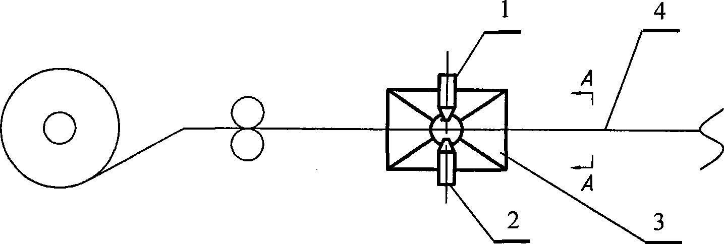
[0018] The utility model relates to a blowing-suction dust collection device for cold-rolled strip steel. The device as figure 1 Shown: It consists of 1 upper nozzle 1, 1 lower nozzle 2 and 1 suction hood 3. The upper nozzle 1 and the lower nozzle 2 are arranged above and below the same side of the steel strip 4 respectively, the installation angle of the upper nozzle 1 and the lower nozzle 2 can be adjusted, and the upper nozzle 1 and the lower nozzle 2 are connected to the compressed gas source through a pipeline; The suction hood 3 is arranged on the other side of the steel strip 4, the suction hood 3 is opposite to the upper nozzle 1 and the lower nozzle 2, and the suction hood 3 is connected with the dust removal pipeline.

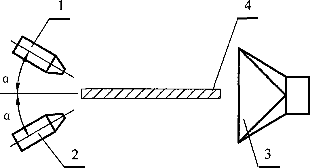
[0019] In this embodiment 1, the gauge pressure of the compressed gas source is 1.5-2Mpa; the installation angle of the upper nozzle 1 and the lower nozzle 2 is: the angle between the vertical plane is as follows: image 3 The shown α is 0~10°, the ...

Embodiment 2

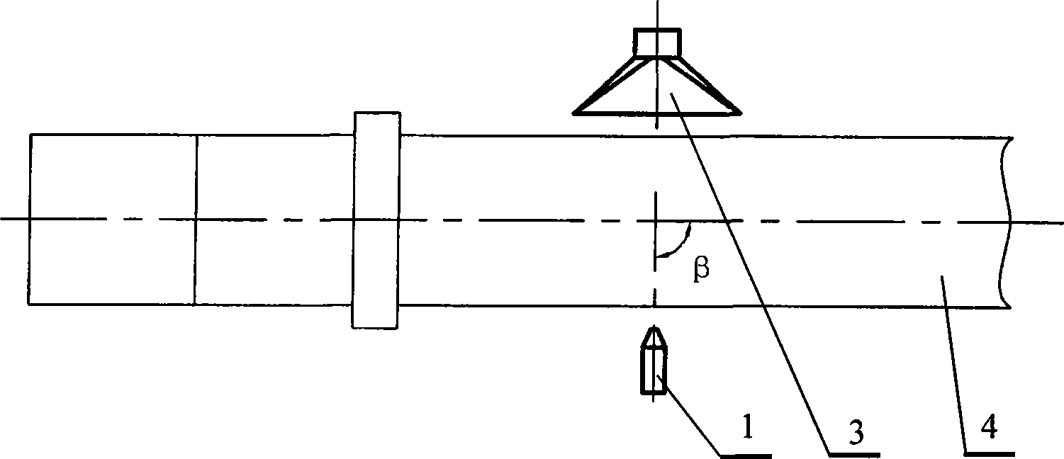
[0021] The utility model relates to a blowing-suction dust collection device for cold-rolled strip steel. The gauge pressure of the compressed gas source is 0.05 ~ 1Mpa; the installation angle of the upper nozzle 1 and the lower nozzle 2 is: the angle between the vertical plane is as follows: image 3 The α shown is 10~15°, and the angle between the horizontal plane is as figure 2 The indicated β is 15 to 70°.

[0022] All the other are with embodiment 1.

Embodiment 3

[0024] The utility model relates to a blowing-suction dust collection device for cold-rolled strip steel. The device is similar to figure 1 As shown, it consists of 2 upper nozzles 1, 2 lower nozzles 2 and 1 suction hood 3. 2 upper nozzles 1 and 2 lower nozzles 2 are respectively arranged above and below the same side of the strip steel 4, the installation angle of the upper nozzle 1 and the lower nozzle 2 can be adjusted, and the 2 upper nozzles 1 and 2 lower nozzles 2 pass through The pipeline is connected with the compressed gas source; the suction hood 3 is arranged on the other side of the steel strip 4, the suction hood 3 is opposite to the upper nozzle 1 and the lower nozzle 2, and the suction hood 3 is connected to the dust removal pipeline.

[0025] In this embodiment 3, the gauge pressure of the compressed gas source is 1-1.5Mpa; the vertical plane installation angles of the two upper nozzles 1 and the two lower nozzles 2 are 0-10° and 10-20° respectively , The ins...


PUM


Abstract

The invention particularly relates to a cold-rolled steel strip push-pull dust collection device. The technical proposal is as follows: the device consists of upper nozzles (1), lower nozzles (2) and a suction hood (3). 1-3 upper nozzles (1) and 1-3 lower nozzles (2) are respectively arranged above or below the same side of a steel strip (4), the setting angle of the upper nozzles (1) and the lower nozzles (2) is adjustable, and the upper nozzles (1) and the lower nozzles (2) are connected with a compressed air source by pipelines; the suction hood (3) is arranged at the other side of the steel strip (4) and opposite to the upper nozzles (1) and the lower nozzles (2), and the suction hood (3) is connected with a dedusting pipeline. The gauge pressure of the compressed air source is 0.05-2MPa; the setting angle of the upper nozzles (1) and lower nozzles (2) includes that the vertical plane included angle alpha is 0-80 degrees, and the horizontal plane included angle beta is 15-165 degrees. The dust collection device has the advantages of good effect of collecting iron scale dusts on the steel strip surface, low energy consumption, simple structure and reliable operation.

Description

technical field [0001] The invention belongs to the technical field of dust source control devices. It specifically relates to a blowing-suction dust collection device for cold-rolled strip steel, especially for controlling the dust generated during the operation of cold-rolled strip steel. Background technique [0002] The cold rolling mill is the final finished product production plant in the iron and steel enterprise, and it is a finished material plant that produces products and benefits. No matter in terms of product quality requirements or environmental benefits, it is required that the cold rolling mill must be clean in the production process. [0003] The main parts that generate dust in the production process of cold rolling mills are pickling unit, skin pass unit and roller grinding unit, etc. Among them, the smoke and dust generated by the leveler and welding machine of the pickling unit are the most serious. Since the strip steel comes out of the hot rolling mil...

Claims


Application Information

Patent Timeline
IPC IPC(8): B21B45/06B08B15/00
Inventor 陈旺生幸福堂王兴东吴高明彭炜梅丹
Owner WUHAN UNIV OF SCI & TECH
Why Eureka
Try Eureka