Micro-displacement sensor based on ring micro-chamber and cantilever beam of integration plane

A technology of micro-displacement sensor and ring-shaped microcavity, which is applied in the direction of instruments, optical waveguide coupling, TV system components, etc., can solve the problems of large measurement error, high system stability requirements, and the inability to use ordinary light sources, etc., to achieve High sensitivity, reduced operation difficulty, compact and simple structure

Inactive Publication Date: 2009-03-18
ZHONGBEI UNIV
View PDF0 Cites 15 Cited by
  • Summary
  • Abstract
  • Description
  • Claims
  • Application Information

AI Technical Summary

Problems solved by technology

However, the optical fiber micro-displacement sensor will cause large measurement errors due to the fluctuation of the output light energy of the light source, the change of the reflectivity of the reflective object surface and the interference of the external environment; the main disadvantage of the laser interferometry to measure the micro-displacement is that the light source must be interference light. , ordinary light sources cannot be used, and the requirements for system stability are extremely high, so it is not suitable for on-site measurement

Method used


Image

  • Micro-displacement sensor based on ring micro-chamber and cantilever beam of integration plane
  • Micro-displacement sensor based on ring micro-chamber and cantilever beam of integration plane
  • Micro-displacement sensor based on ring micro-chamber and cantilever beam of integration plane

Examples


example

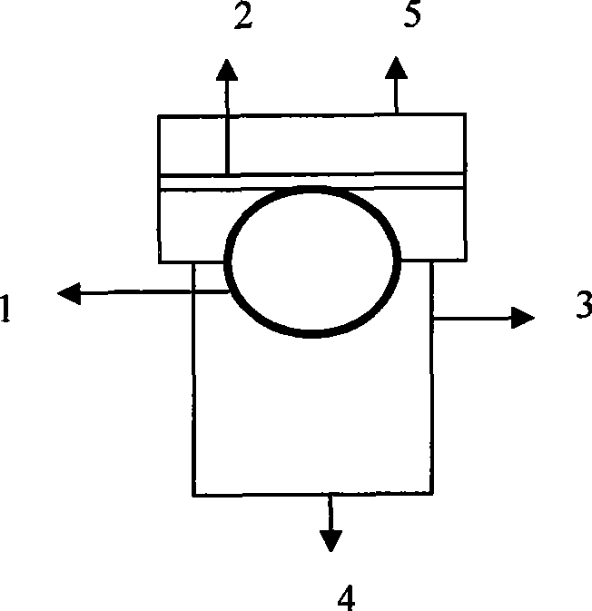
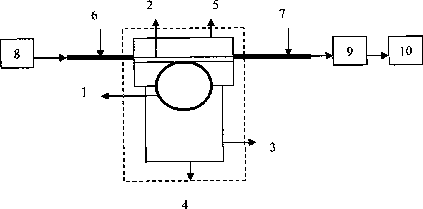
[0029] (1) Planar annular microcavity: use MEMS processing technology to oxidize SiO2 on the surface of Si, and process to form a planar annular microcavity. The material is SiO2, the radius is 20-25um, and the thickness of the ring is 1-2um. In order to obtain a planar annular microcavity with a small half-width value, deep modulation depth, and high quality factor, the inner diameter of the planar annular microcavity is selected as 20um in this example.

[0030] (2) Optical waveguide: the material is SiO2, and the geometric shape is a slender cuboid with a width of 1-2um and a thickness of 0.75-1um.

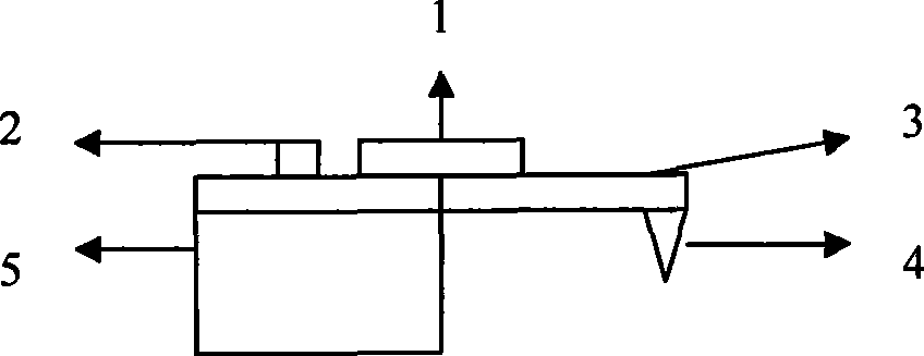
[0031] (3) Cantilever beam: the material is GaAs, the geometric shape is cuboid, wherein the design dimensions of the rectangle can be: length 100-400um, width 20-50um, thickness 0.4-10um.

[0032] Since the stress detection accuracy of the cantilever beam increases with the increase of the length / thickness ratio, in order to obtain high sensitivity, it is advisable to prepare ...


PUM


Abstract

The invention relates to a micrometric displacement sensor based on an integrated planar ring-shaped micro cavity and a cantilever beam, which comprises a planar ring-shaped micro cavity, an optical waveguide, a substrate, an incidence fiber connected with the optical waveguide and an emergence fiber connected with the optical waveguide. The planar ring-shaped micro cavity is coupled with the optical phase of the optical waveguide. The micrometric displacement sensor is characterized in that the micrometric displacement sensor also comprises a cantilever beam and a probe; one end of the cantilever beam is connected with the substrate and the other end of the cantilever beam is a free end; the probe is positioned in the middle of the front part of the free end on the lower surface of the cantilever beam, and both the cantilever beam and the probe are formed by etching; and both the planar ring-shaped micro cavity and the optical waveguide are etched on the upper surface of the cantilever beam. The micrometric displacement sensor is made by using a modern MEMS processing technology, can be used in complex magnetic field environments, vacuum environments, can be used for measuring wide range of objects, including the measurement on the surfaces of biological cells as well as the surfaces of metals and non-metals, and has the measuring precision of 10<-4> angstroms.

Description

technical field [0001] The invention belongs to the technical field of micro-electromechanical systems, and mainly relates to a micro-displacement sensor, in particular to a micro-displacement sensor based on an integrated planar annular microcavity and a cantilever beam. Background technique [0002] In the field of micro-nano technology, micro-electromechanical system technology and precision control technology, micro-displacement sensors are one of the more important components in micro-electromechanical systems. For the measurement methods of micro-displacement, there are mainly electrical measurement technology and optical measurement technology at present. Among them, the displacement sensors based on electrical measurement technology mainly include electromagnetic sensors and eddy current sensors. The measurement accuracy of the electromagnetic sensor is very low, which cannot reach the micron level, and is greatly affected by the electromagnetic field. The measurem...

Claims


Application Information

Patent Timeline
Patent Type & Authority Applications(China)
IPC IPC(8): G01B11/02B81B7/02
Inventor 张文栋熊继军薛晨阳闫树斌吉喆严英占王少辉王宝花姜国庆
Owner ZHONGBEI UNIV
Why Eureka
Try Eureka