Optical element transmitted spectrum automatic surface scanning and measuring apparatus and method

A transmission spectrum and optical element technology, which is applied in the field of optical element transmission spectrum automatic surface scanning measurement device, can solve the problems of large size and quality of components, inability to ensure the safety of measurement components, and inability to place them, so as to ensure safety and command input operation Convenience, effect of size increase

Inactive Publication Date: 2009-03-18
SHANGHAI INST OF OPTICS & FINE MECHANICS CHINESE ACAD OF SCI
View PDF0 Cites 6 Cited by
  • Summary
  • Abstract
  • Description
  • Claims
  • Application Information

AI Technical Summary

Problems solved by technology

Like the optical components used in some large optical systems, due to the large size and mass of the components, the sample chamber of the existing spectrophotometer cannot be placed, and if the components are placed vertically, the safety of the measuring components cannot be guaranteed. Therefore, the exi...

Method used


Image

  • Optical element transmitted spectrum automatic surface scanning and measuring apparatus and method
  • Optical element transmitted spectrum automatic surface scanning and measuring apparatus and method
  • Optical element transmitted spectrum automatic surface scanning and measuring apparatus and method

Examples


Embodiment Construction

[0030] The present invention will be further described below in conjunction with the embodiments and accompanying drawings, but the protection scope of the present invention should not be limited thereby.

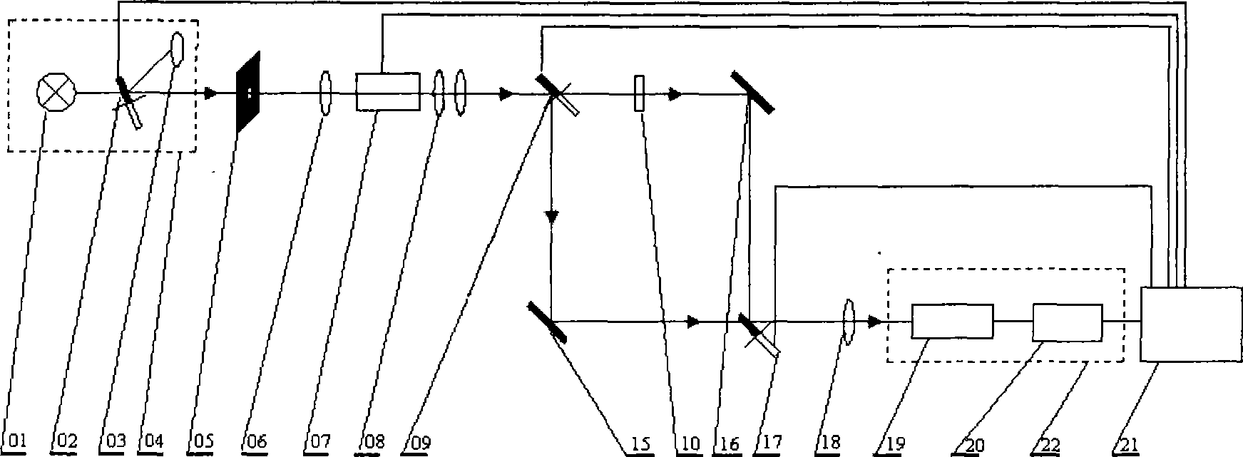
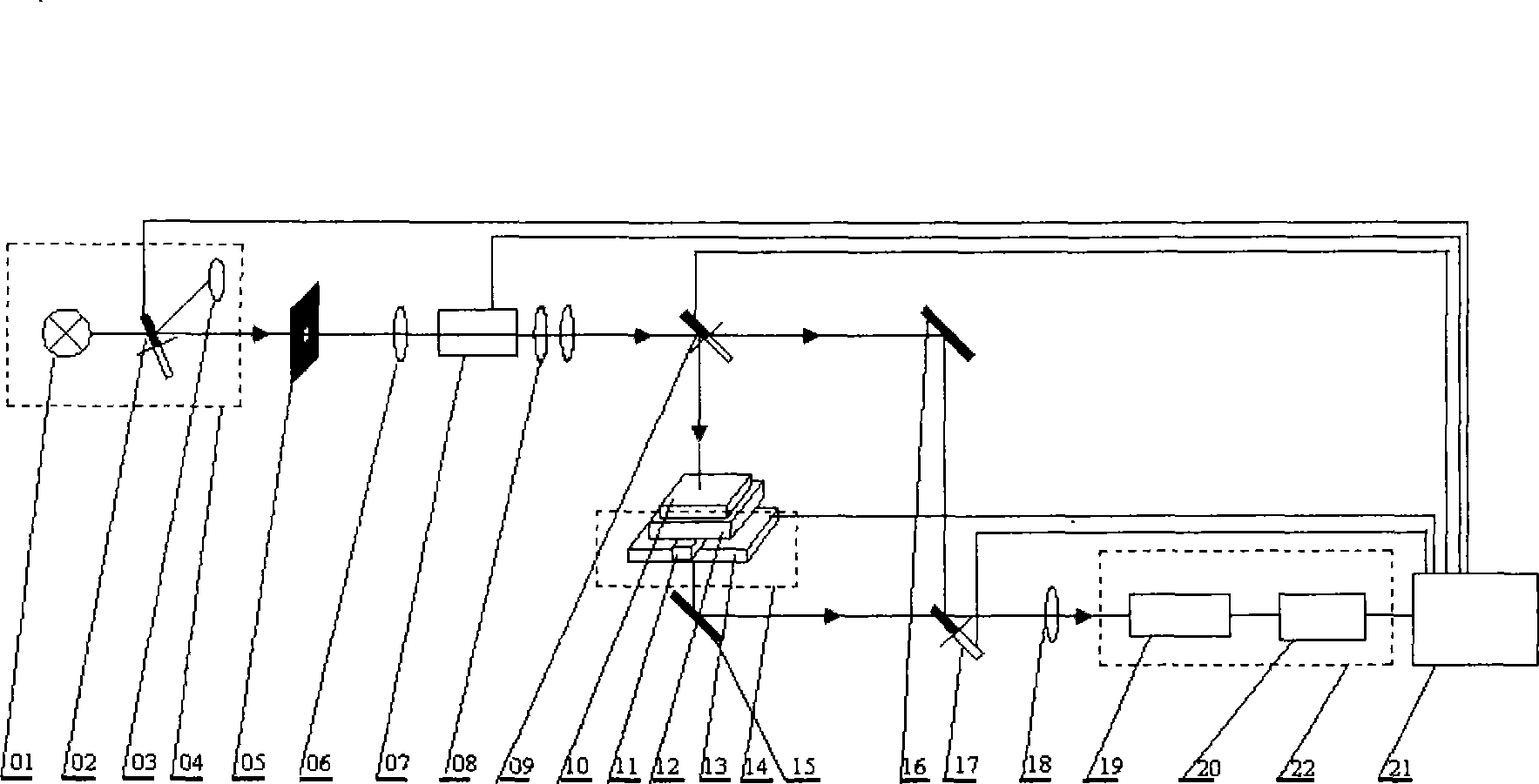
[0031] see first figure 2 , figure 2 It is a schematic structural diagram of an automatic surface-scanning measurement device for the transmission spectrum of an optical element of the present invention, and is also a schematic structural diagram of an embodiment of the present invention. It can be seen from the figure that the automatic surface-scanning measurement device for the transmission spectrum of an optical element of the present invention comprises a light source 04, an aperture 05. First converging mirror 06, monochromatic system 07, collimating lens group 08 and second half mirror 09, reference optical path, measurement optical path, third half mirror 17, second converging mirror 18, sample 10. Signal receiving system 22 and computer 21, the vertical light pa...


PUM


Abstract

The invention relates to a device and a method for automatic surface scanning and measuring of a transmitted spectrum of an optical element. The device comprises a light source, a light diaphragm, a first convergent mirror, a monocolor system, a collimating lens assembly, a second half-reflection pellicle mirror, a reference path, a measuring light path, a third half-reflection pellicle mirror, a second convergent mirror, a sample to be tested, a signal receiving system and a computer. The device and the method are characterized in that the measuring light path measures the horizontally-placed sample to be tested; and the computer is provided with control software, and is connected with a first half-reflection pellicle mirror, the second half-reflection pellicle mirror, the third half-reflection pellicle mirror, the monocolor system, a two-dimensional electric translational platform and the signal receiving system respectively through signal wires. The method realizes the transmitted spectrum measurement of the optical element, can measure the optical element with the maximum dimension of 400 mm x 600 mm, and realizes the automatic surface scanning and measuring of the optical element through the control of the control software of the computer.

Description

technical field [0001] The invention relates to spectrum measurement, in particular to an automatic surface-scanning measurement device and method for optical element transmission spectrum capable of measuring large-scale optical elements. Background technique [0002] Spectrophotometer is the most common measuring instrument for measuring the spectral characteristics of optical components. It can measure the reflectance, transmittance, absorption and other spectral characteristics of optical components. [0003] The optical path diagram of the existing spectrophotometer is as follows figure 1 As shown, the light source 04 is composed of a halogen lamp 01, a deuterium lamp 03 and a first half-mirror 02, the rotation axis of the first half-mirror 02 is at 22.5° to the main optical path, and the optical axis of the deuterium lamp 03 is at an angle to the first half-mirror 02. The rotation axis of the half mirror 02 is 22.5°; the light emitted by the light source 04 becomes mo...

Claims


Application Information

Patent Timeline
IPC IPC(8): G01J3/28G01M11/02
Inventor 朱美萍范正修易葵
Owner SHANGHAI INST OF OPTICS & FINE MECHANICS CHINESE ACAD OF SCI
Why Eureka
Try Eureka