Method of manufacturing polarization maintaining optical fiber

A technology for polarization-maintaining optical fibers and manufacturing methods, which is applied to cladding optical fibers, manufacturing tools, glass manufacturing equipment, etc., can solve problems such as easy fiber breakage, difficult optical fibers, and insufficient cladding out-of-roundness, etc., so as to improve mechanical strength, The effect of improving the mechanical performance and satisfying the service life

Active Publication Date: 2009-03-18
YANGTZE OPTICAL FIBRE & CABLE CO LTD
View PDF2 Cites 18 Cited by
  • Summary
  • Abstract
  • Description
  • Claims
  • Application Information

AI Technical Summary

Problems solved by technology

[0008] Panda-shaped polarization-maintaining optical fiber is manufactured using the perforated composite rod process. In order to ensure that the stress rod is smoothly inserted into the hole of the perforated preform, the diameter of the hole needs to be larger than the outer diameter of the stress rod. Due to the lack of part of the glass material between the stress rod and the hole , will lead to the deterioration of the cladding roundness of the produced polarization maintaining fiber, which will affect the application of the fiber
[0009] Using the process scheme proposed by the patent ZL 03805091.9, there are always some problems in actual production: First, due to the use of the method of shaping the outer surface of the preform into two or more planes, the gap between the planes and between the planes and the planes Ridges appear between the curved surfaces. The existence of such ridges seriously affects the mechanical properties of the optical fiber, making the combined preform extremely prone to fiber breakage during the drawing process and the subsequent screening process of the optical fiber; second, patent ZL 03805091.9 In the process plan, the main process of adjusting the roundness of the optical fiber cladding is the automatic adjustment when the preform shrinks to a diameter of 3mm. In order to complete this process, low-speed and low-tension drawing conditions must be used. This drawing condition is in actual production. , which greatly reduces the production efficiency of the optical fiber, and also has a greater impact on the strength of the polarization-maintaining optical fiber, making it difficult for the optical fiber to pass the 1% screening; third, using the above-mentioned process, the cladding of the polarization-maintaining optical fiber produced The out-of-roundness can only be controlled at the level of 1%. This kind of cladding out-of-roundness is not enough in the application of some devices. Device production requires the cladding out-of-roundness of the optical fiber to reach the level of 0.5% and below

Method used


Image

  • Method of manufacturing polarization maintaining optical fiber
  • Method of manufacturing polarization maintaining optical fiber
  • Method of manufacturing polarization maintaining optical fiber

Examples


Embodiment 1

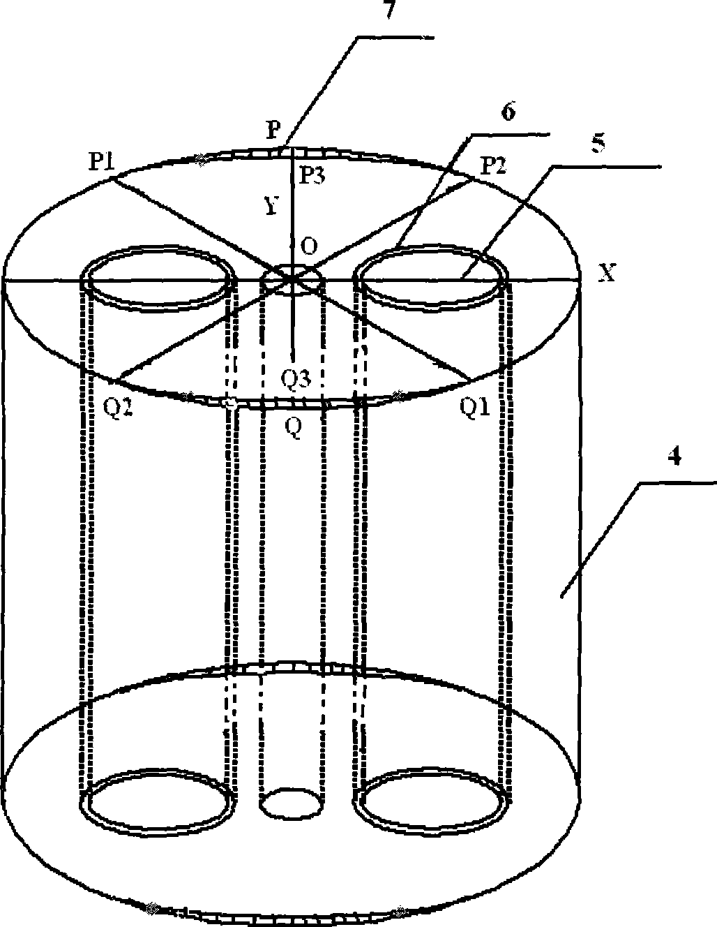
[0047] Use PCVD method to deposit and manufacture optical fiber core rods and stress rods, insert the core rods into the quartz sleeves, clean and dry them, and then go to the drawing tower to stretch the core rods and sleeve tubes into integrated optical fiber preform rods with a diameter of 50 mm. Holes were symmetrically drilled on both sides of the core of the manufactured optical fiber preform, and the diameter of the holes was 16 mm. At the same time, the diameter of the stress rod manufactured by deposition is adjusted to 15.2 mm by mechanical or corrosion methods. Since the 15.2mm diameter stress rod is inserted into the 16mm hole, the gap between the stress rod and the hole is 0.4mm. Using the HF acid etching process, the side of the perforated preform perpendicular to the direction of the double holes is immersed in the acid solution (such as image 3 P 1 PP 2 surface), the depth of immersion in the acid solution gradually changes from 0mm to 0.6mm, that is, the p...

Embodiment 2

[0049] Use PCVD method to deposit and manufacture optical fiber core rods and stress rods, insert the core rods into the quartz sleeves, clean and dry them, and then go to the drawing tower to stretch the core rods and sleeve tubes into integrated optical fiber preform rods with a diameter of 50 mm. Holes were symmetrically drilled on both sides of the core of the manufactured optical fiber preform, and the diameter of the holes was 16 mm. At the same time, the diameter of the stress rod manufactured by deposition is adjusted to 15.2 mm by mechanical or corrosion methods. Since the 15.2mm diameter stress rod is inserted into the 16mm hole, the gap between the stress rod and the hole is 0.4mm. Using the HF acid etching process, the side of the perforated preform perpendicular to the direction of the double holes is immersed in the acid solution (such as image 3 P 1 PP 2 surface), the depth of immersion in the acid solution gradually changes from 0mm to 0.8mm, that is, the p...

Embodiment 3

[0051]Use PCVD method to deposit and manufacture optical fiber core rods and stress rods, insert the core rods into the quartz sleeves, clean and dry them, and then go to the drawing tower to stretch the core rods and sleeve tubes into integrated optical fiber preform rods with a diameter of 50 mm. Holes were symmetrically drilled on both sides of the core of the manufactured optical fiber preform, and the diameter of the holes was 16 mm. At the same time, the diameter of the stress rod manufactured by deposition is adjusted to 15.2 mm by mechanical or corrosion methods. Since the 15.2mm diameter stress rod is inserted into the 16mm hole, the gap between the stress rod and the hole is 0.4mm. Using the HF acid etching process, the side of the perforated preform perpendicular to the direction of the double holes is immersed in the acid solution (such as image 3 P 1 PP 2 surface), the depth of immersion in the acid solution gradually changes from 0mm to 1.0mm, that is, the pe...


PUM

PropertyMeasurementUnit
surface roughnessaaaaaaaaaa
diameteraaaaaaaaaa
diameteraaaaaaaaaa

Abstract

The invention relates to a production method for polarization maintaining fibers, comprising an optical fiber perform rod with a fiber core and a clad, wherein the clad at two sides of the fiber core of the optical fiber perform rod are symmetrically processed with two longitudinal penetration holes parallel with the fiber core; two stress rods are respectively inserted into the two holes on the optical fiber perform rod to form a combination optical fiber perform rod; performing the combination optical fiber on an optical fiber drawing tower to draw the fiber to obtain a panda-type polarization maintaining fiber. The production method is characterized in that the upper and the lower circumferences of parallel to the center connecting line of the two holes of the optical fiber perform rod and the insertion stress rod are removed with part of the clad in a transition curve type, to make the radial section of the optical fiber perform rod in an oval or ellipse form. The invention quantifies the correction area and size of the perform rod, therefore, under the surface tension force, the combination perform rod can be instantly fused and reduced into a polarization maintaining fiber with good surface circularity to confirm the clad non circularity of produced polarization maintaining fibers under 0.5%.

Description

technical field [0001] The invention relates to a method for manufacturing a polarization-maintaining optical fiber. In particular, it relates to a method for manufacturing panda-type polarization-maintaining optical fiber. The application of the manufacturing method can reduce the out-of-roundness of the cladding of the panda-type polarization-maintaining optical fiber, and improve the mechanical strength and production efficiency of the polarization-maintaining optical fiber. The invention can be used to manufacture polarization-maintaining optical fibers and single-mode single-polarization optical fibers working at various wavelengths. Background technique [0002] Polarization maintaining fiber is a kind of special fiber. Polarization maintaining fiber, that is, polarization maintaining fiber, is a type of fiber that maintains the linear polarization direction of the transmitted light. Polarization-maintaining optical fiber can be applied in many fields, such as multi...

Claims


Application Information

Patent Timeline
Patent Type & Authority Applications(China)
IPC IPC(8): G02B6/02C03B37/012
CPCC03B37/01217C03B2203/31Y02P40/57
Inventor 汪洪海涂峰童维军
Owner YANGTZE OPTICAL FIBRE & CABLE CO LTD
Why Eureka
Try Eureka