
Solar cell component

A technology of solar cells and components, applied in electrical components, circuits, photovoltaic power generation, etc., can solve the problems of solar cell reception and waste, and achieve the effect of improving photoelectric conversion efficiency

Inactive Publication Date: 2009-03-18
HONG FU JIN PRECISION IND (SHENZHEN) CO LTD +1
View PDF0 Cites 7 Cited by
  • Summary
  • Abstract
  • Description
  • Claims
  • Application Information

AI Technical Summary

Problems solved by technology

[0005] However, the substrates of general solar cells are made of materials such as monocrystalline silicon, polycrystalline silicon or glass. Most of the solar cells based on these materials can only receive the sun's radiation in a fixed direction, which will have a large part of the radiation energy. Wasted because it cannot be received by the solar cell

Method used


Image

  • Solar cell component
  • Solar cell component
  • Solar cell component

Examples


Embodiment Construction

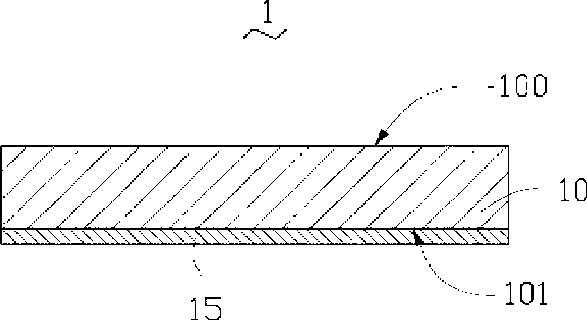
[0014] See figure 1 , the first embodiment of the present invention provides a solar cell assembly 1 , and the solar cell assembly 1 includes a flexible solar cell 10 . The flexible solar cell 10 includes a first surface 100 for receiving solar radiation energy, and a second surface 101 opposite to the first surface 100 . A shape memory alloy layer 15 (Shape Memory Alloys layer, SMA layer) is formed on the second surface 101 .

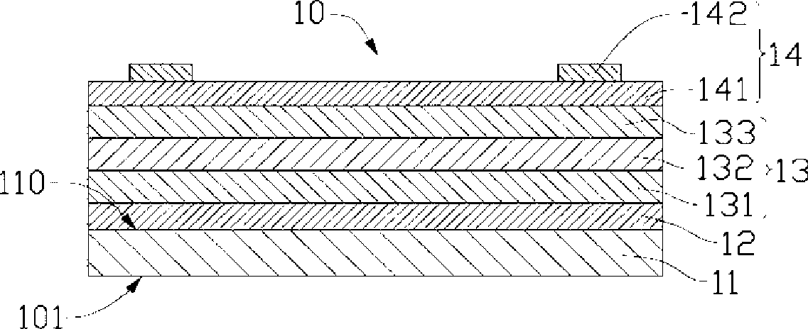
[0015] See figure 2 , the flexible solar cell 10 includes a substrate 11 having a first surface 110 and a second surface 101 . A first electrode layer 12 , a semiconductor structure layer 13 , and a second electrode layer 14 opposite in polarity to the first electrode layer 12 are sequentially formed on the first surface 110 of the substrate 11 .

[0016] In this embodiment, the substrate 11 is a flexible aluminum-magnesium alloy foil (Al-Mg alloy foil), and the thickness of the substrate is approximately between 10 μm and 100 μm. The material of ...


PUM


Abstract

The invention relates to a solar cell assembly, which comprises a flexible solar cell, wherein the flexible solar cell comprises a first surface for receiving solar radiation energy, and a second surface which is corresponding to the first surface. A shape memory body alloy layer is attached on the second surface, in order to make the flexible solar cell change shapes as the shape changes of the shape memory body alloy layer.

Description

technical field [0001] The invention relates to a solar cell assembly, in particular to a solar cell assembly capable of changing shapes. Background technique [0002] The solar cell mainly applies the principle of photoelectric conversion, and its structure mainly includes a substrate and a P-type semiconductor material layer and an N-type semiconductor material layer arranged on the substrate. [0003] Photoelectric conversion refers to the process in which photons of solar radiation energy are converted into electrical energy through semiconductor materials (see "Grownjunction GaAs solar cell", Shen, C.C.; Pearson, G.L.; Proceedings of the IEEE, Volume 64, Issue 3, March 1976Page(s ): 384-385). When sunlight shines on a semiconductor, part of it is reflected off the surface, and the rest is absorbed or transmitted by the semiconductor. Some of the absorbed light turns into heat energy, and some photons collide with the atomic valence electrons that make up the semicondu...

Claims


Application Information

Patent Timeline
Patent Type & Authority Applications(China)
IPC IPC(8): H01L31/042H01L31/045H01L31/052H02S30/20
CPCY02E10/52H02S30/20H01L31/0522H01L31/054Y02B10/12H01L31/045Y02E10/50Y02B10/10
Inventor 陈杰良
Owner HONG FU JIN PRECISION IND (SHENZHEN) CO LTD
Learn More