Screw conveyor for discharging reduced iron from rotary hearth reduction furnace

A screw conveyor and rotary furnace bottom technology, which is applied to hearth furnaces, furnaces, furnace components, etc., can solve the problems of reducing the weight of the screw conveyor, adding spring parts, and increasing costs, so as to improve the water cooling effect and prolong wear The effect of life and equipment cost reduction

Active Publication Date: 2009-03-18
NIPPON STEEL & SUMIKIN ENG CO LTD +1
View PDF4 Cites 1 Cited by
  • Summary
  • Abstract
  • Description
  • Claims
  • Application Information

AI Technical Summary

Problems solved by technology

[0011] However, in the device described in Patent Document 4, in order to make the pressing force of the screw conveyor within a predetermined range, it is necessary to adjust the pressing force of the screw conveyor determined by the lifting cylinder.
Here, when the pressing force of the screw conveyor is incorrectly adjusted, the apparent self-weight of the screw conveyor may be excessively reduced
Moreover, when springs are used to reduce the pressing force of the screw conveyor determined by the lifting cylinder, parts such as springs are added, which increases the cost.

Method used


Image

  • Screw conveyor for discharging reduced iron from rotary hearth reduction furnace
  • Screw conveyor for discharging reduced iron from rotary hearth reduction furnace
  • Screw conveyor for discharging reduced iron from rotary hearth reduction furnace

Examples


Embodiment Construction

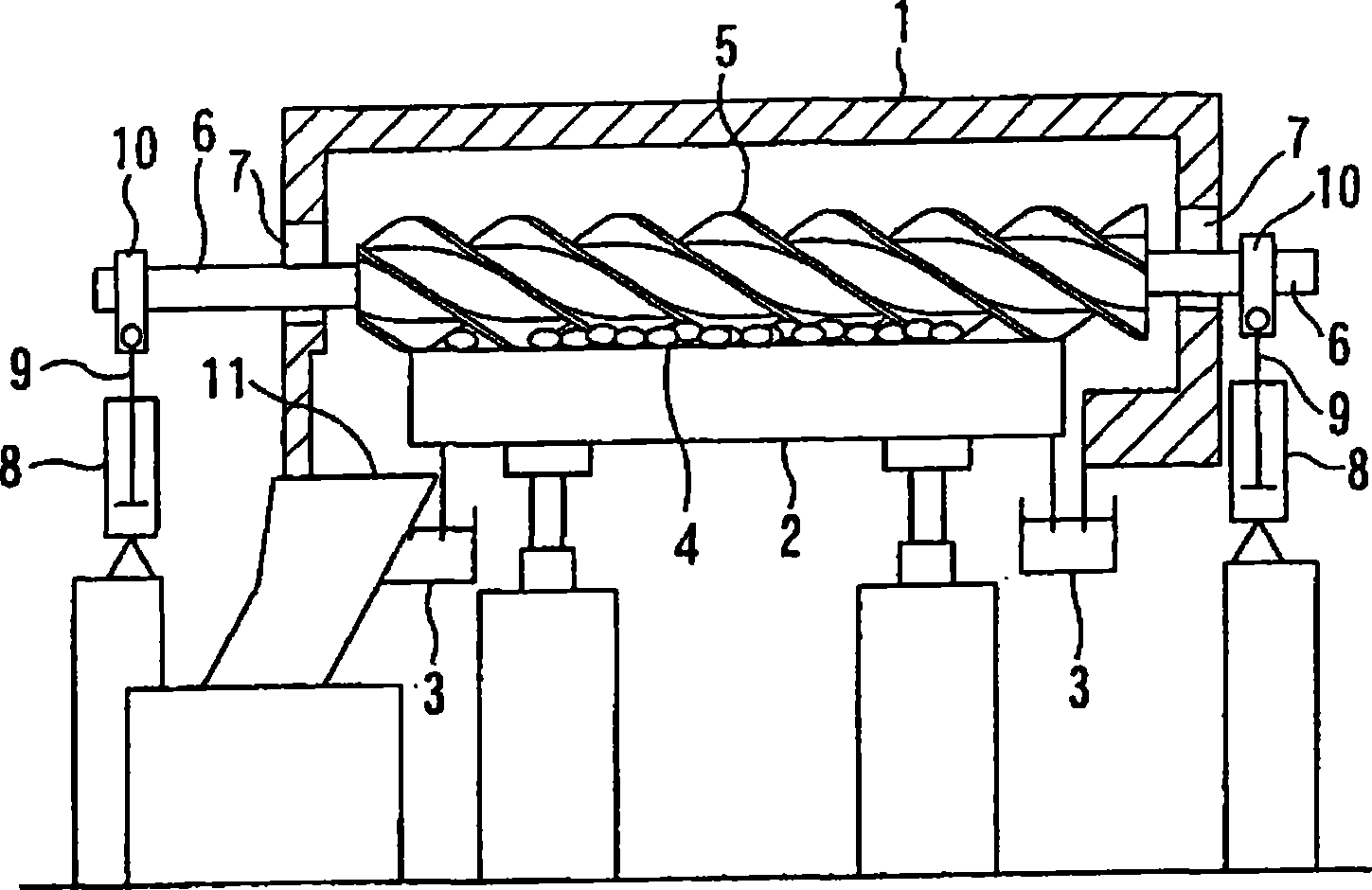
[0025] figure 1 It is a schematic diagram showing an example of a rotary hearth type reduction furnace in which the screw conveyor for discharging reduced iron (hereinafter referred to as "screw conveyor") of the present invention is disposed.

[0026] The rotary furnace bottom 2 is rotatably arranged in the horizontal plane below the furnace body 1 of the rotary hearth type reduction furnace, and the furnace body 1 and the rotary furnace bottom 2 are water-sealed by the ring-shaped water-sealed pipeline 3 so as to maintain the inside of the furnace. atmosphere of.

[0027] The two ends of the rotary shaft 6 of the screw conveyor 5 pass through the long hole 7 of the furnace body 1, and the piston rod 9 of the cylinder 8 arranged outside the furnace supports the screw conveyor 5 so as to be able to move up and down through the bearing 10. 5 is used to discharge the reduced iron 4 obtained after the reduction treatment of the pellets to the outside. The bearing 10 is fixedly...


PUM


Abstract

The invention provides a screw conveyor for discharging reduced iron from a rotary hearth reduction furnace in which the rate of operation of the rotary hearth reduction furnace can be enhanced by prolonging the abrasion life of the screw blades of screw conveyor thereby reducing maintenance frequency of the screw conveyor. In the screw conveyor (5) which is disposed in the rotary hearth reduction furnace for producing reduced iron by loading a pellet composed of a metal oxide and a carbon material onto a rotary hearth rotating in a horizontal plane and then by heating (reduction), and which discharges reduced iron to the outside of the furnace, a rotating shaft and screw blades formed spirally on the outer circumference of the rotating shaft are provided, and the lead angle theta (rad) of the screw blade (5a) is set to satisfy the condition 0.6 rad <= theta <= 0.79rad. Furthermore, the ratio (h / D) between the height (h) of the screw blade and the outside diameter (D) of the screw conveyor is set smaller than 0.2, and the ratio (t / h) between the thickness (t) and the height (h) of the screw blade is set at 0.12 or above.

Description

field of invention [0001] The present invention relates to a screw conveyor for discharging reduced iron. The screw conveyor is arranged in a rotary hearth type reduction furnace and is used for discharging reduced iron to the outside of the furnace. Background technique [0002] A rotary hearth type reduction furnace has been used in the manufacture of reduced iron. The rotary hearth type reduction furnace makes iron ore, iron powder and other metal oxides and carbon materials into pellets, and the pellets are loaded on the bottom of the rotary furnace and heated (reduced) to produce reduction iron, and the rotary hearth is rotated on a horizontal plane in a rotary hearth type reduction furnace (refer to Patent Documents 1, 2, and 3). [0003] Figure 5 It is a schematic diagram showing an example of a rotary hearth type reduction furnace. exist Figure 5 In this method, reduced iron is manufactured by charging pellets from a pellet loading port 22 onto a rotary hearth 21...

Claims


Application Information

Patent Timeline
Patent Type & Authority Applications(China)
IPC IPC(8): F27D3/08C21B13/10F27B9/16F27B9/39
CPCF27B9/30F27B9/16F27D3/08F27B9/39C21B13/0046C21B13/105
Inventor 岛真司中山俊孝永富正秀
Owner NIPPON STEEL & SUMIKIN ENG CO LTD
Why Eureka
Try Eureka