
Back pressure type blind-hole bricks die

A technology of blind hole bricks and molds, which is applied in the direction of molds, forming indenters, ceramic forming cores, etc., can solve the problems of mandrel design structure, unreasonable processing technology, affecting the strength of bricks, and breaking the mandrel. Vibrating motor and movable plate, reducing mold cost and avoiding the effect of bending and breaking

Inactive Publication Date: 2009-03-25
XIANGYANG SANJIN MOLD
View PDF0 Cites 7 Cited by
  • Summary
  • Abstract
  • Description
  • Claims
  • Application Information

AI Technical Summary

Problems solved by technology

[0003]The existing molds for blind hole bricks formed by presses have the following disadvantages: 1. Because the mandrel is in the mold cavity, it is easy to feed unevenly, which affects the strength of the bricks, and serious Can not be pressed
2. Relying on the limit column to control the depth of the blind hole reduces the number of formed bricks and reduces the efficiency of the press
3. The connection between the mandrel and the movable plate, and the movable plate and the middle frame is unreasonable. The length of the mandrel is very long, which easily causes the misalignment of the upper mold core and the mandrel. During the pressing process, the mold core bends the mandrel, which seriously breaks the mandrel.
4. The design structure and processing technology of the mandrel are unreasonable, and the service life of the mandrel is short
5. It is inconvenient to replace the mandrel
6. Because the mandrel is in the mold cavity, it is not easy to distribute the material, and accessories such as vibration motors need to be added, which increases the mold manufacturing cost

Method used


Image

  • Back pressure type blind-hole bricks die
  • Back pressure type blind-hole bricks die
  • Back pressure type blind-hole bricks die

Examples


Embodiment Construction

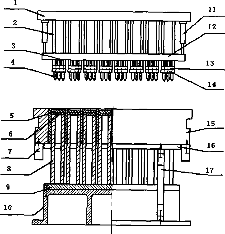
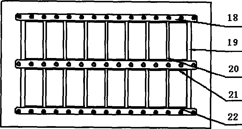
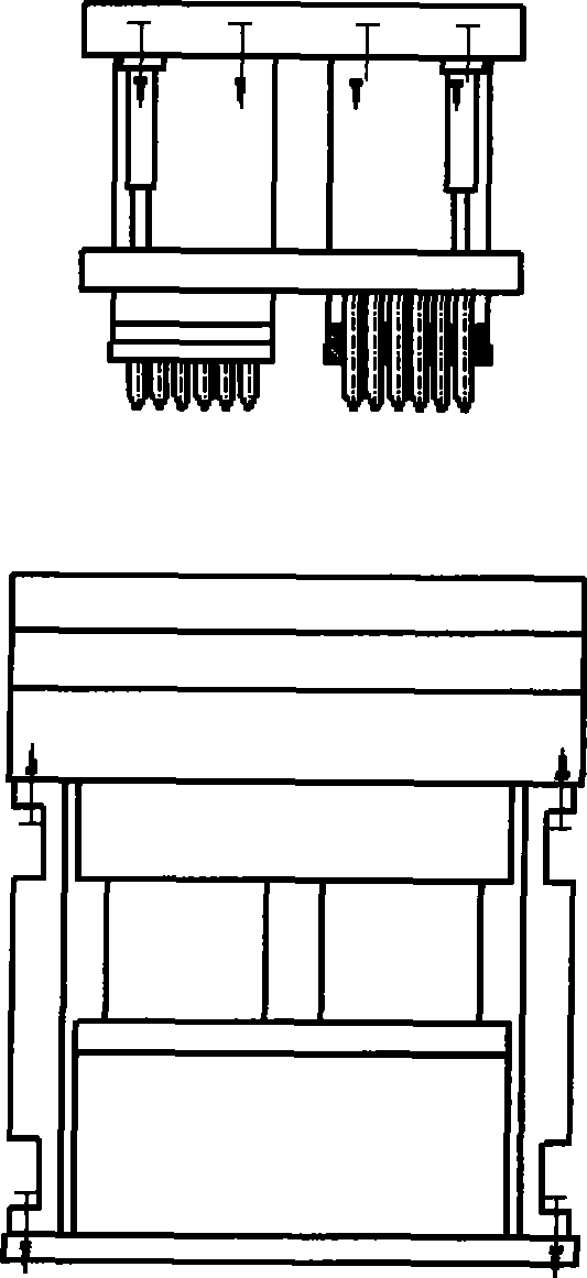
[0022] Such as figure 1 , image 3 As shown, the blind hole brick mold at least includes an upper mold, a lower mold and a middle frame 15, and the upper mold includes an upper template 1, an upper mold base 2, a mandrel backing plate 3, a mandrel 4, an oil cylinder 11, a movable plate 12, and an upper mold The backing plate 13 and the upper mold core 14, the mandrel 4 is connected to the movable plate 12 through the mandrel backing plate 3, and the movable plate 12 is connected to the upper template 1 through the oil cylinder 10. When the mold is working, the oil circuit of the oil cylinder 11 is connected with the press , must be linked with the press, the upper mold core 14 is connected with the upper mold base 2 through the upper mold backing plate 13, and the upper mold base 2 is fixed below the upper template 1; the lower mold includes the lower mold core 5, the lower mold backing plate 13, The push rod 8, the bottom plate 9 and the base 10, the lower mold core 5 are co...


PUM


Abstract

The invention discloses a counter-pressure blind-hollow brick die, the die at lease includes an upper die, a lower die, a middle frame, a core shaft and a cylinder. The upper die is connected with a upper moving beam of a press, the lower die is connected with a lower base by the lower die core through a lower die backing plate, a push rod and a bottom plate. The middle frame is directly connected with a lower moving beam of the press. The invention uses the mode that the core shaft is in the upper die, the length of the core shaft can be reduced, thereby a high positioning accuracy can be achieved, the effect of protecting the core shaft is realized, the press bending and the pressing fracture of the core shaft are avoided, meanwhile the core shaft can be replaced conveniently, the working efficiency of the die is improved, the core shaft is moved relatively to the upper die core so as to play a molding function when forming a brick base and to protect the integration of the brick base during demoulding, because the core shaft uses a reasonable structure design and processing technique, the positioning accuracy and the wear resistance can be improved, so that the service life and reliability of the die are improved.

Description

technical field [0001] The invention relates to a blind-hole brick mold formed by a hydraulic oil cylinder, in particular to a mold capable of pressing fly ash blind-hole bricks. Background technique [0002] Fly ash is one of the largest industrial wastes in my country, and the annual slag discharge in China has reached 30 million tons at this stage. With the development of the power industry, the discharge of fly ash from coal-fired power plants is increasing year by year. If a large amount of fly ash is not treated, it will generate dust and pollute the atmosphere; if it is discharged into the water system, it will cause river silting, and the toxic chemicals in it will also cause harm to human beings and organisms. Therefore, the processing and utilization of fly ash has attracted widespread attention. At the same time, due to the impact of land prices, there are more and more high-rise buildings in my country, all of which are frame structures, and the walls do not ne...

Claims


Application Information

Patent Timeline
Patent Type & Authority Applications(China)
IPC IPC(8): B28B3/04B28B7/16B28B7/22B28B7/30
Inventor 李传龙
Owner XIANGYANG SANJIN MOLD
Learn More