Microwave continuous graphite expansion apparatus

A technology of puffing device and microwave, applied in the field of microwave continuous graphite puffing device, can solve the problems that materials cannot continuously enter and exit the microwave heater, the L-shaped reflector and the furnace body collide with the building, the L-shaped reflector is troublesome to load and unload, etc., and the structure is simple. , The effect of low equipment cost and reliable operation

Inactive Publication Date: 2009-03-25
任崇桂
View PDF6 Cites 13 Cited by
  • Summary
  • Abstract
  • Description
  • Claims
  • Application Information

AI Technical Summary

Problems solved by technology

[0010] The patent No. 02143336.4 microwave continuous heating device is designed to heat molded objects such as ceramics. Although the microwave generator can work continuously, the materials cannot continuously enter and exit the microwave heater, and the L-shaped reflective plate is troublesome to install and unload. If there is a slight misalignment during operation, the L-shaped reflector may collide with the furnace body.
In addition, since graphite is a scaly powder, it is not suitable for transportation on L-shaped reflectors.
[0011] Patent No. 200720146485.0 is a drum-type microwave continuous heating device for solid materials. Although the device can realize the continuous in and out of materials, it relies on the gravity of the materials. Due to the large volume and light weight of expanded graphite (200-300ml / g), a single Feeding by gravity cannot guarantee uniform feeding
In addition, the device does not consider the problem of microwave leakage

Method used


Image

  • Microwave continuous graphite expansion apparatus
  • Microwave continuous graphite expansion apparatus

Examples


Embodiment Construction

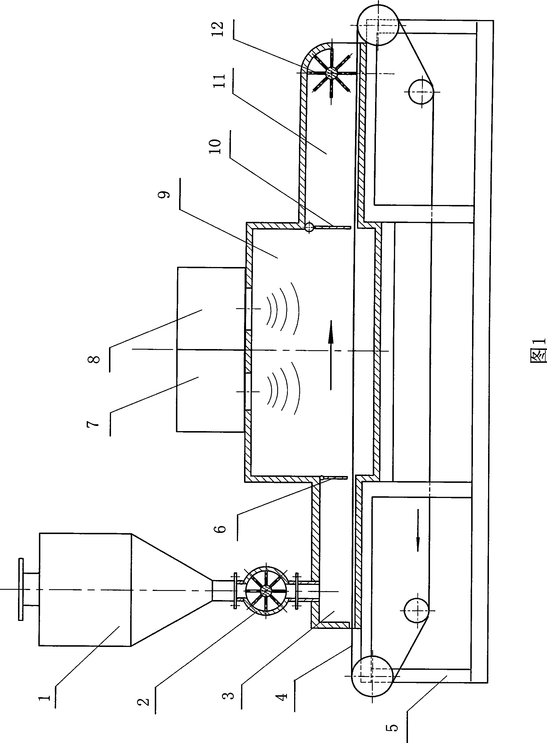
[0022] The present invention will be further described below in conjunction with accompanying drawing and specific embodiment:

[0023] The microwave graphite continuous heating puffing device of the present invention is shown in Fig. 1, comprises: graphite hopper 1, rotary feeder 2, microwave feed absorption chamber 3, belt conveyer 4, bracket 5, feed absorption chamber microwave reflection plate 6, left Microwave generator 7, right microwave generator 8, microwave heating puffing chamber 9, microwave reflection plate 10 of discharge absorption chamber, discharge absorption chamber 11, rotary discharger 12 and other parts.

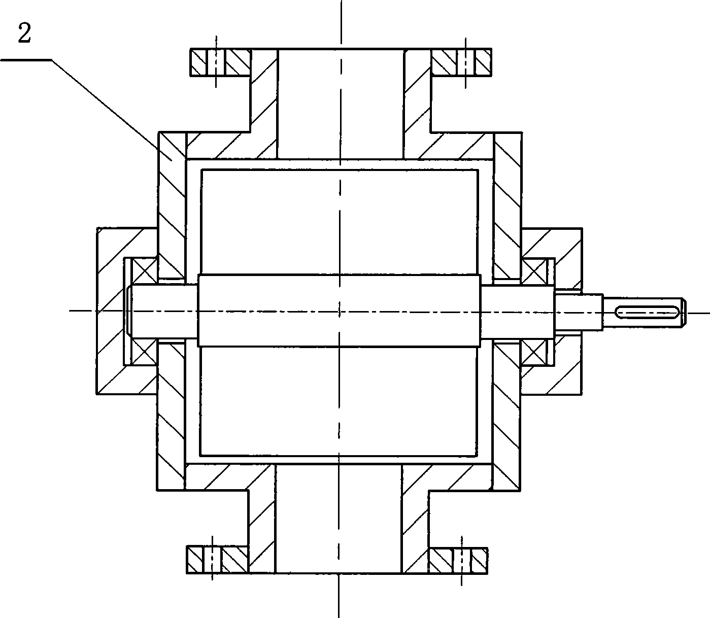
[0024] Microwave continuous graphite expansion device of the present invention, as shown in Figure 1, figure 2 As shown, it includes: a hopper 1, the bottom of the hopper 1 is connected with a rotary feeder 2, the upper and lower ends of the shell of the rotary feeder 2 are respectively provided with a feed inlet and a discharge port, and the center of th...


PUM

PropertyMeasurementUnit
widthaaaaaaaaaa
thicknessaaaaaaaaaa

Abstract

A microwave continuous graphite puffing device comprises a hopper; the lower part of the hopper is connected with a rotary feeder which is provided with a drive shaft and a rotary drum; a rotary vane is fixed on the rotary drum; the lower end of the rotary feeder is connected with a microwave feeding absorption chamber, the right end of which is connected with a microwave heating puffing chamber; a left microwave generator and a right microwave generator are arranged on the upper part of the microwave heating puffing chamber, the right end of which is connected with a microwave discharging absorption chamber; and the right end of the microwave discharging absorption chamber is provided with a rotary discharger. The conveyor belt of a belt conveyor respectively passes through the microwave feeding absorption chamber, the microwave heating puffing chamber, and the microwave discharging absorption chamber. The left end of the microwave heating puffing chamber is rotatablely connected with a feeding absorption chamber microwave baffle-board and the right end thereof is rotatablely connected with a discharging absorption chamber microwave baffle-board. The invention has the advantages of easy control, reliable operation, large material treatment quantity, can effectively prevent microwave leakage, and can realize continuous feeding and discharging as well as continuous microwave heating puffing graphite.

Description

technical field [0001] The invention relates to a graphite expansion device, in particular to a microwave continuous graphite expansion device for continuous expansion of the scaly graphite by using microwaves as a heat source after the flaky graphite is treated by a chemical intercalation method. Background technique [0002] There are four patents related to graphite expansion furnaces and two patents related to microwave continuous heating devices that can be found on the patent website of the State Intellectual Property Office. [0003] ①The utility model patent with the patent number of 96242354.8 is a hearth of graphite puffing furnace. It includes a graphite cylinder, and there is a layer of isolation layer on the inner and outer cylindrical surfaces and both ends of the graphite cylinder to isolate the direct contact between the atmosphere and the graphite cylinder. Filling layers are respectively arranged between the cylindrical surface and the outer isolation laye...

Claims


Application Information

Patent Timeline
Patent Type & Authority Applications(China)
IPC IPC(8): C01B31/04
Inventor 任崇桂
Owner 任崇桂
Why Eureka
Try Eureka