Acoustic logging instrument of novel acoustic array structure

A well logging instrument and array structure technology, which is applied in seismology for well logging records, borehole/well components, earthwork drilling and production, etc., can solve the problem of increasing the unsafety of on-site operations, reducing reliability, and increasing the length of instruments To improve the sensitivity and measurement accuracy, simplify the structure of the instrument, and improve the sound field intensity

Inactive Publication Date: 2009-03-25
CHINA NAT OFFSHORE OIL CORP +1
View PDF1 Cites 16 Cited by
  • Summary
  • Abstract
  • Description
  • Claims
  • Application Information

AI Technical Summary

Problems solved by technology

[0004] 1. The sound system is relatively long, and the longer sound system will increase the length of the instrument. The disadvantages are as follows: 1. For the need of sound insulation, sound insulation grooves need to be carved on the casing of the sonic logging tool, which reduces the strength of the instrument. An excessively long sound system will further reduce the overall mechanical strength of the instrument and increase the unsafety of on-site operations. Second, because logging instruments usually perform slam operations, that is, multiple instruments are connected in series to complete the measurement. In order to ensure the integrity of the measurement, When drilling, it is necessary to increase the depth of the length of the drilling tool string, so that the uppermost tool can also measure the destination layer, so too long tool length requires a deeper drilling depth, which increases drilling costs;
[0005] 2. The control of the instrument is complicated. Since two transmitters need to be equipped with two transmitter circuit systems, it increases the difficulty of designing supporting control circuits, reduces reliability, and introduces more noise sources into the signal acquisition system;
[0006] 3. The two transmitting transducers cannot be launched at the same time, and the time interval is 50 milliseconds, so that in the cementing quality logging operation, the CBL measurement and the VDL measurement cannot be accurately at the same depth point

Method used


Image

  • Acoustic logging instrument of novel acoustic array structure
  • Acoustic logging instrument of novel acoustic array structure
  • Acoustic logging instrument of novel acoustic array structure

Examples


Embodiment Construction

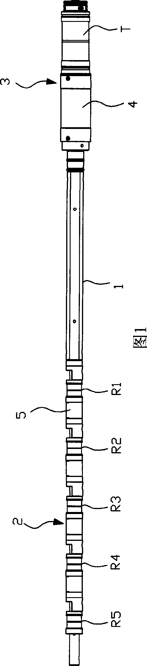
[0022] As shown in Figure 1, the present invention includes: a base 1, the base 1 is made of a circular mandrel made of epoxy resin material, the base 1 includes a receiving area 2 and a transmitting area 3, and the receiving area 2 is arranged at equal intervals in sequence There are five receiving transducers R1, R2, R3, R4, R5, one transmitting transducer T is set in the transmitting area, and a high-voltage pulse excitation part 4 for driving the transmitting transducer T is also set in the transmitting area 3.

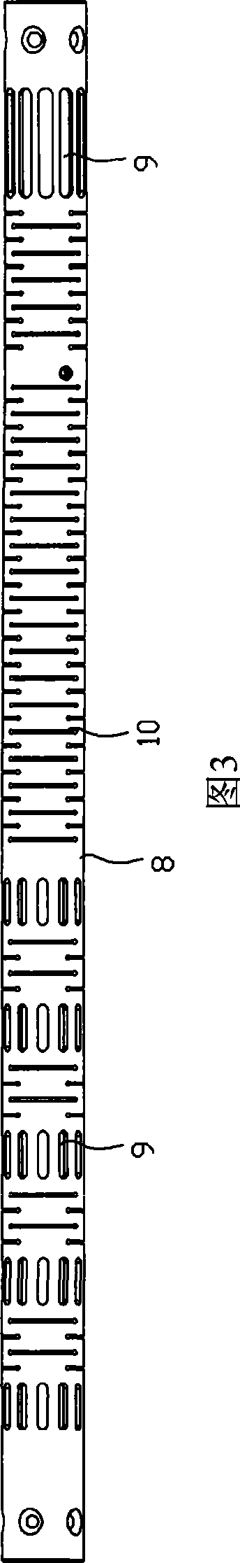
[0023] The receiving transducers R1, R2, R3, R4, R5 and the transmitting transducer T are composed of two annular piezoelectric ceramics connected in parallel, and the width of the receiving transducers with R1, R2, R3, R4, R5 is 0-23KHZ. The receiving transducers R1, R2, R3, R4, R5 are arranged at equal intervals with a spacing of 6 inches, and the adjacent receiving transducers R1, R2, R3, R4, R5 are replaced by ring-shaped sound insulation materials. Sound Loop...


PUM


Abstract

The invention discloses a novel acoustic logging instrument with a sonic system array structure, which comprises a pedestal. The pedestal comprises a receiving zone and a transmitting zone, wherein the receiving zone is provided with five receiving transducers at equal intervals in turn; and the transmitting zone is provided with a transmitting transducer and a high-voltage pulse excitation part which drives the transmitting transducer. The novel acoustic logging instrument adopts the structure of one transmitting transducer and five receiving transducers, greatly simplifies the structure of the instrument and reduces the manufacture cost; moreover, the transmitting transducer adopts a double-crystal parallel mechanism to improve the sound source incentive efficiency and signal receiving sensibility, and has higher measuring accuracy in slow formation. When the instrument is used to measure cementing quality, the receiving transducer closest to the transmitting transducer can complete CBL amplitude logging, and the receiving transducer farthest from the transmitting transducer can complete VDL full wave logging.

Description

technical field [0001] The invention relates to the technical field of oilfield geological exploration, in particular to a novel acoustic logging instrument with an acoustic system array structure. Background technique [0002] Acoustic logging tools are used in the oilfield geological exploration process to measure the sound velocity of rocks around the oil well, that is, the sound wave transmission speed of rocks. Combined with the data of other measuring instruments such as formation resistivity, natural gamma ray, formation rock density, formation neutron porosity, etc., the formation lithology around the wellbore and formation rock porosity can be evaluated in detail. It plays an important role and is one of the necessary downhole instruments for conventional logging equipment. [0003] Currently widely used structures are 2-transmission-2-reception structure and 2-transmission-4-reception structure. Patent application 200510043741.9 discloses a 2-transmit and 4-recei...

Claims


Application Information

Patent Timeline
Patent Type & Authority Applications(China)
IPC IPC(8): E21B49/00G01V1/40
Inventor 刘西恩陶爱华余戈人
Owner CHINA NAT OFFSHORE OIL CORP
Why Eureka
Try Eureka