Solar low-temperature thermal power generation and cold- thermal co-feeding system

A combined cooling and heating technology and low-temperature heating technology, applied in the field of solar energy utilization, can solve the problems that solar thermal power generation systems are not suitable for small-scale applications, cannot be provided to users at the same time, and the efficiency of solar thermal power generation is low, so as to achieve environmental protection and enhance Stability and persistence, easy-to-build effects

Inactive Publication Date: 2009-03-25
UNIV OF SCI & TECH OF CHINA
View PDF2 Cites 37 Cited by
  • Summary
  • Abstract
  • Description
  • Claims
  • Application Information

AI Technical Summary

Problems solved by technology

[0007] In order to solve the problems of low operating efficiency of existing flat plate collectors, vacuum tube collectors, etc. above medium temperature (such as 60°C) and high concentration ratio heat collectors such as trough, tower, and dish, which need to track the sun’s trajectory and high cost; To solve the problem of low efficiency of the existing low-temperature solar thermal power generation; to solve the problem that the existing solar thermal power generation system is not suitable for small-scale applications and cannot provide users with electric energy, cold energy, heating and hot water at the same time, the present invention aims to provide a Solar low-temperature thermal power generation and combined cooling and heating system

Method used


Image

  • Solar low-temperature thermal power generation and cold- thermal co-feeding system
  • Solar low-temperature thermal power generation and cold- thermal co-feeding system
  • Solar low-temperature thermal power generation and cold- thermal co-feeding system

Examples


Embodiment

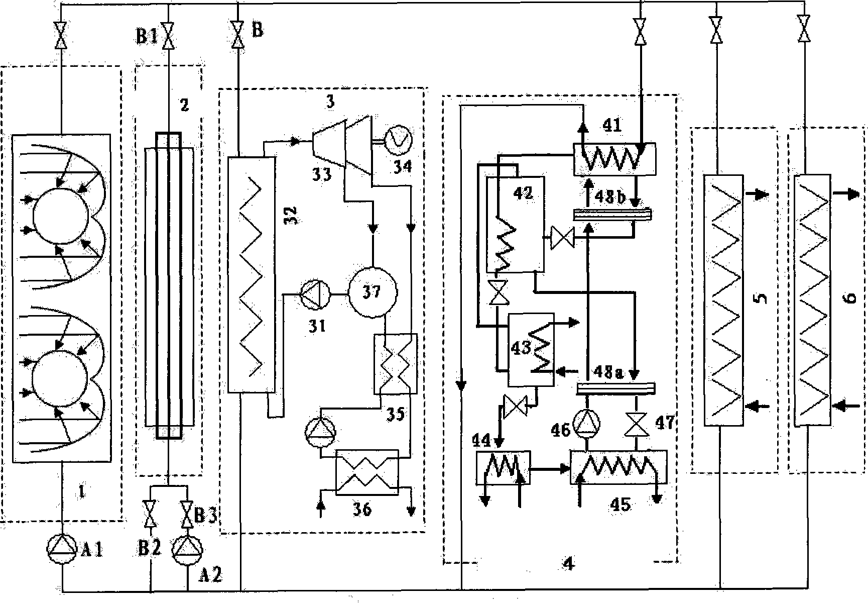
[0036] The solar low-temperature thermal power generation and combined cooling and heating system includes a compound parabolic collector system 1, a phase change heat storage system 2, an organic Rankine cycle power generation system 3, an absorption refrigeration system 4, a hot water supply system 5 and a heating supply system 6 subsystems, the six subsystems are connected in parallel, see figure 1 , figure 2 , image 3 and Figure 5 .

[0037] The organic Rankine cycle power generation system includes a pump 31, an evaporator 32, a steam turbine 33, a generator 34, a regenerator 35, a condenser 36 and a mixer 37, wherein the inlet of the steam turbine 33 is connected to the outlet of the organic working medium of the evaporator 32, The outlet of the steam turbine 33 is connected to the mixer 37 through the regenerator 35, and the middle part of the steam turbine 33 is provided with an air extraction port, which is connected to the other port of the mixer 37 through a p...


PUM


Abstract

The invention relates to a solar low-temperature thermal power generation and combined heat and cold supply system, which solves the problems that the lower-temperature solar thermal power generation has lower efficiency, is unsuitable for small-scale application and can not supply electric energy, cold energy, warm air and hot water simultaneously. The system consists of a composite paraboloid heat collector system, a phase-change heat storage system, an organic Rankine cyclic power generating system, an absorption and refrigeration system, a hot water supply system and a warm air supply system which are connected in parallel. An inlet of a steam turbine of the power generating system is communicated with an organic working substance outlet of an evaporator; an outlet of the steam turbine is communicated with a mixer through a heat regenerator; an air suction port of the middle part of the steam turbine is communicated with another end port of the mixer through a pipeline; the other side of the heat regenerator is connected in series with a condenser; a third port of the mixer is communicated with an organic working substance inlet of the evaporator through a pump; and the output end of the steam turbine is connected with a power generator. The system has high operating efficiency and three combined supplies of heat, power and cold, is suitable for small-scale application, is easy to build and low in cost, does not need to consume one-off energy and is favorable for environmental protection.

Description

technical field [0001] The invention relates to the field of solar energy utilization, in particular to solar thermal power generation and combined cooling and heating systems. Background technique [0002] Solar thermal power generation technology is a major means for human beings to develop and utilize solar energy. Since the oil crisis in the early 1970s, major developed countries in the world such as the United States, Spain, Germany, Switzerland, France, Italy, and Japan have taken solar thermal power technology as the focus of national research and development, and gradually began to develop solar thermal power generation on a large scale. During the 10 years from 1981 to 1991, more than 20 megawatt-level solar thermal power test stations with an installed capacity of more than 500kW were built all over the world. Due to the large investment per unit capacity and the difficulty in reducing the cost, the construction of solar thermal power stations has gradually fallen...

Claims


Application Information

Patent Timeline
Patent Type & Authority Applications(China)
IPC IPC(8): F03G6/06F24J2/04F28D20/02F24D17/00F24D3/00
CPCY02E10/46Y02E10/44Y02E60/145Y02E60/14
Inventor 裴刚季杰李晶
Owner UNIV OF SCI & TECH OF CHINA
Why Eureka
Try Eureka