
Solar driven coaxial traveling wave starting and standing wave cooling device

A refrigeration device and solar energy technology, applied in the direction of solar thermal devices, solar thermal power generation, heating devices, etc., can solve the problem of limiting the overall efficiency of the thermoacoustic engine refrigeration system, the efficiency is not ideal for standing wave thermoacoustic engines, and the failure to realize solar real-time Tracking and other issues to achieve the effect of easy access, low price, and high bearing strength

Inactive Publication Date: 2010-10-06
XI AN JIAOTONG UNIV
View PDF6 Cites 0 Cited by
  • Summary
  • Abstract
  • Description
  • Claims
  • Application Information

AI Technical Summary

Problems solved by technology

However, he failed to achieve real-time tracking of the sun, and he could not work continuously throughout the day with high efficiency; and he used a standing wave thermoacoustic engine with unsatisfactory efficiency, which limited the overall efficiency of the entire thermoacoustic engine refrigeration system
[0004] The feedback loop setting of the current traveling wave thermoacoustic engine makes the rear resonant cavity and the thermoacoustic core orthogonal, and there are problems such as uncompact structure, large space required, and inconvenient real-time tracking of solar energy and docking with thermoacoustic refrigerators.
However, the actual solar-driven coaxial structure traveling wave engine-standing wave refrigeration device requires compact structure, easy docking, and easy tracking, and the existing traveling wave thermoacoustic engine can no longer meet the requirements

Method used


Image

  • Solar driven coaxial traveling wave starting and standing wave cooling device
  • Solar driven coaxial traveling wave starting and standing wave cooling device
  • Solar driven coaxial traveling wave starting and standing wave cooling device

Examples


Embodiment Construction

[0017] The present invention will be described in further detail below in conjunction with the accompanying drawings.

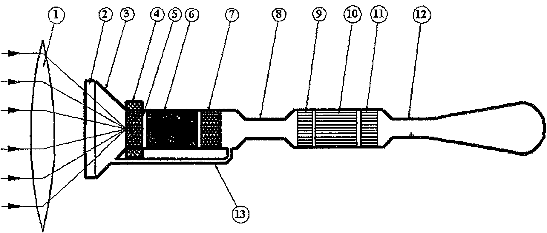
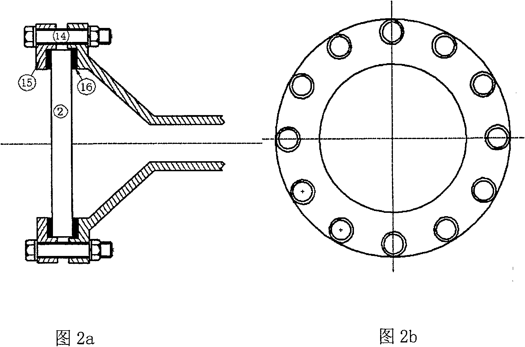
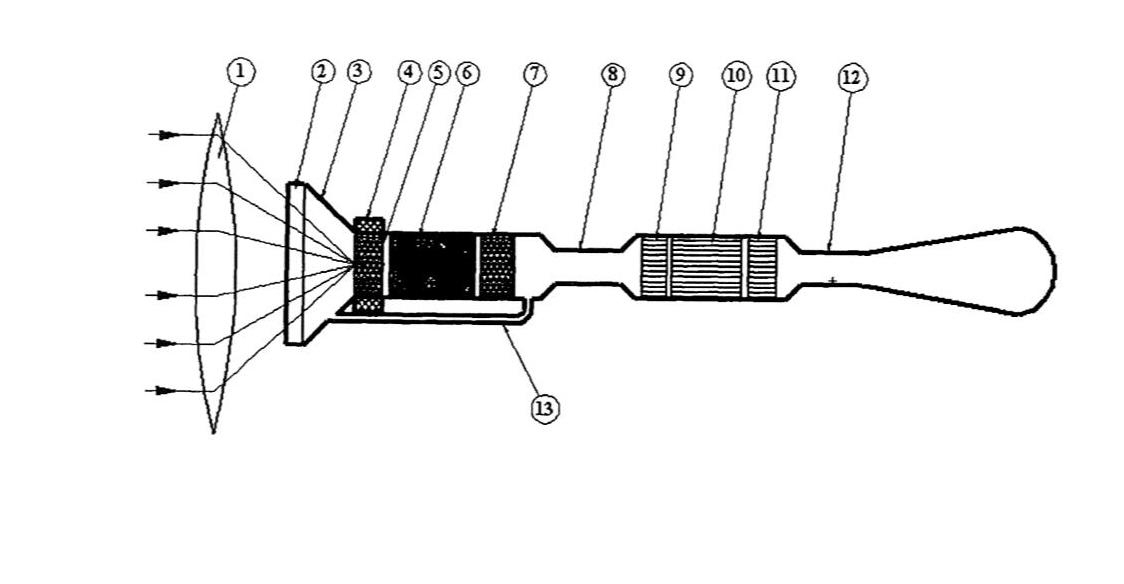
[0018] see figure 1 , the present invention includes: a traveling wave thermoacoustic engine with a coaxial structure and a standing wave thermoacoustic refrigerator with a coaxial structure, wherein the traveling wave thermoacoustic engine includes: a hot end heat exchanger 5, a plate stack 6, a cooling End heat exchanger 7 and feedback pipe 13; Standing wave thermoacoustic refrigerator includes: room temperature heat exchanger 9, plate stack 10, cold end heat exchanger 11, in the cold end heat exchanger 7 and standing wave thermoacoustic engine A resonant tube 8 is arranged between the room temperature heat exchangers 9 of the wave thermoacoustic refrigerator, wherein the resonant tube 8 is installed coaxially with the hot end heat exchanger 5, the plate stack 6, and the cold end heat exchanger 7 of the traveling wave thermoacoustic engine , the front end ...


PUM


Abstract

The invention relates to a solar-driven coaxial traveling wave starting and standing wave refrigerating device, which comprises a traveling wave thermoacoustic engine and a standing wave thermoacoustic refrigerating machine with coaxial structures, and also comprises a resonatron which is connected between the traveling wave thermoacoustic engine and the standing wave thermoacoustic refrigeratingmachine, a solar light-accumulating device and a solar light-transmitting device which are arranged in front of the traveling wave thermoacoustic engine, a resonant cavity which is arranged on the rear of the standing wave thermoacoustic refrigerating machine, and a fused salt annular box which is coated on the outside of a heat exchanger on the hot end of the traveling wave thermoacoustic engine. Due to organic axial arrangement of the traveling wave thermoacoustic engine and the standing wave thermoacoustic refrigerating machine, the solar-driven coaxial traveling wave starting and standingwave refrigerating device has the advantages of compact structure and high efficiency; fused salt which is coated on the outside of the heat exchanger on the hot end of the engine is an ideal thermalcapacitance, thereby having the advantage of constant heating temperature; and a light-transmitting enclosed body on the front end of the engine uses quartz glass, thereby having the advantages of high-efficiency transmittance and prevention of low-temperature internal infrared radiation from passing through.

Description

technical field [0001] The invention belongs to the field of gas refrigeration and low temperature, and in particular relates to a solar-driven coaxial traveling wave engine-standing wave refrigeration device. Background technique [0002] Thermoacoustic heat engine is a new type of heat engine that uses thermoacoustic effect to convert heat energy into sound energy. There are no moving parts in the system, which has the characteristics of simple structure and low cost. High-grade thermal energy is used as the driving heat source; and the cooling scheme of the combination of thermoacoustic engine and thermoacoustic refrigerator has high reliability because there are no moving parts, and has broad application prospects. [0003] On the other hand, as the form of energy becomes increasingly severe, thermoacoustic systems that use renewable energy such as solar energy as a driving heat source have emerged as the times require. In 2000, Hofler of the U.S. Naval Research Institu...

Claims


Application Information

Patent Timeline
Patent Type & Authority Patents(China)
IPC IPC(8): F25B23/00F03G7/00F24J2/00
CPCY02E10/40
Inventor 何雅玲沈超李玉光
Owner XI AN JIAOTONG UNIV
Learn More