Method of heat accumulation and heat accumulation system

A heat storage system and heat storage technology, applied in the direction of heat storage equipment, chemical instruments and methods, heat exchanger types, etc., can solve the problems of high heat storage density and reduction of heat storage, so as to improve heat transfer efficiency and increase heat transfer efficiency. The amount of output and the effect of increasing the amount of heat extracted

Inactive Publication Date: 2009-03-25
PANASONIC CORP
View PDF5 Cites 17 Cited by
  • Summary
  • Abstract
  • Description
  • Claims
  • Application Information

AI Technical Summary

Problems solved by technology

[0006] In this way, when using conventional sensible heat storage and latent heat storage, the heat storage material used according to the temperature of the heat source is limited, and there is a problem that high heat storage density cannot be ensured in a wide temperature range. In the case of chemical heat storage, heat energy must be input from the outside during the heat release process, so there is a disadvantage that the heat storage capacity is substantially reduced

Method used


Image

  • Method of heat accumulation and heat accumulation system
  • Method of heat accumulation and heat accumulation system
  • Method of heat accumulation and heat accumulation system

Examples


no. 1 Embodiment approach

[0084] Hereinafter, a heat storage method according to a first embodiment of the present invention will be described with reference to the drawings.

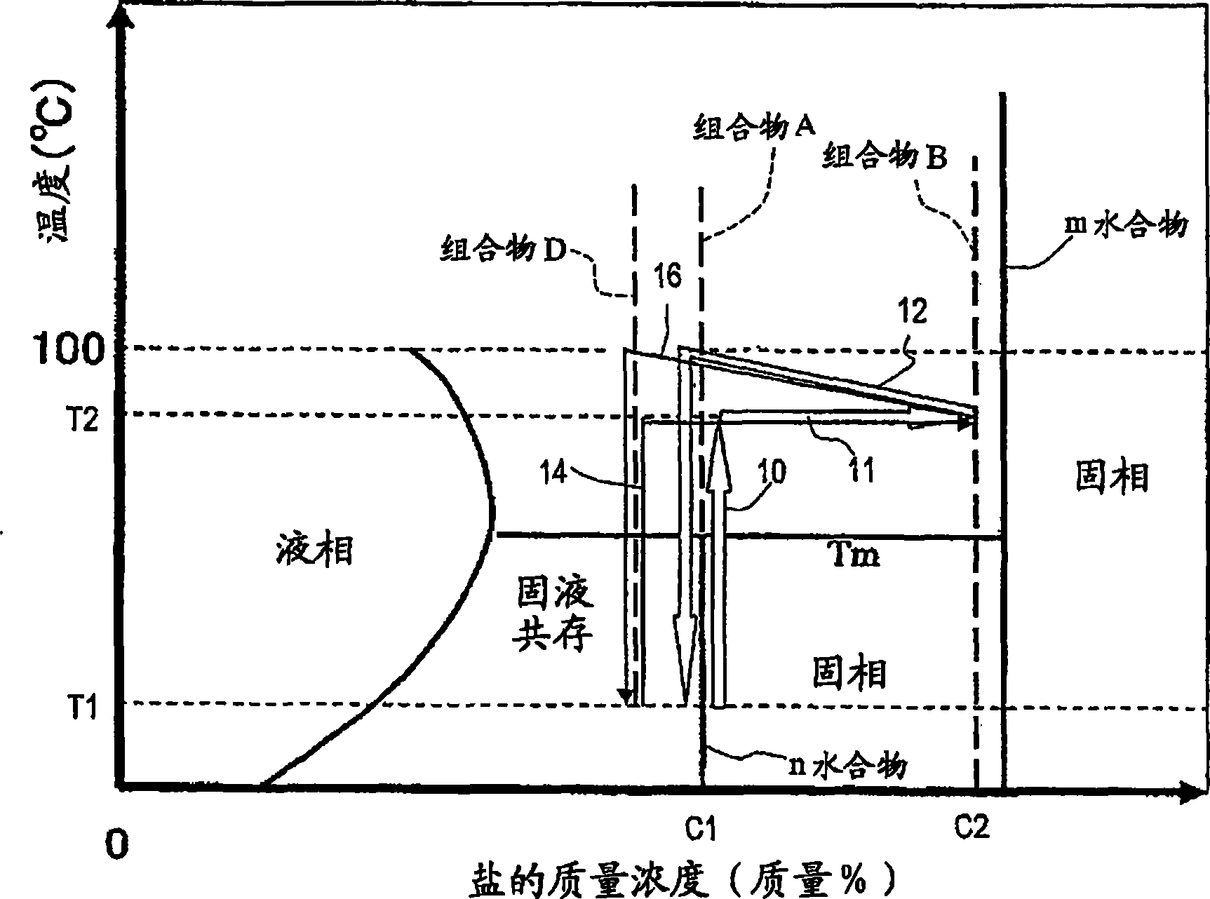
[0085] figure 1 It is a figure for demonstrating an example of the heat storage and heat release process in this embodiment. figure 1 In , the abscissa represents the concentration of the composition, and the ordinate represents the temperature, illustrating a phase diagram showing the state of existence of phases at each composition of inorganic salt and water.

[0086] In this example, as the first composition, a composition A (concentration of inorganic salt: c1) of an n-hydrate in a solid phase at temperature T1 was used. The temperature T1 is defined as room temperature, for example.

[0087] In the heat storage process, as shown by the arrow 10, first if the temperature of the n-hydrate is heated from the temperature T1 to a temperature T2 higher than the phase transition temperature Tm, the dehydration reaction of the n...

no. 2 Embodiment approach

[0104] Hereinafter, a heat storage method according to a second embodiment of the present invention will be described with reference to the drawings.

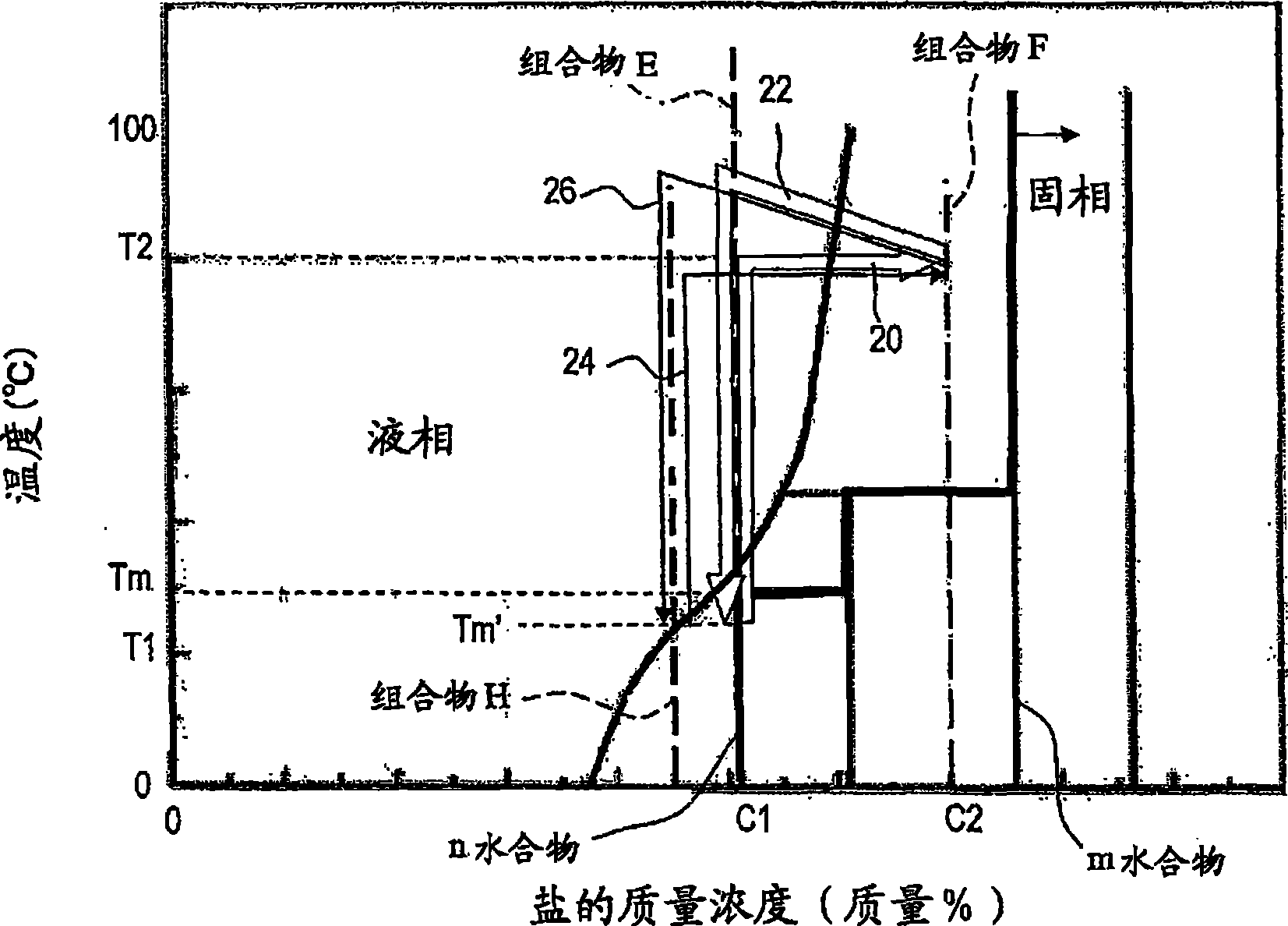
[0105] This embodiment differs from the above-described embodiments in that the first composition becomes the second composition through a liquid-phase monomer state during the heat storage process. That is, in the aforementioned embodiment, when the first composition is heated to the temperature T2, it becomes a solid-liquid coexistence state, and the second composition is obtained by separating water from the first composition in the solid-liquid coexistence state, and In this embodiment, the 1st composition turns into an aqueous solution when heated to temperature T2, and the 2nd composition is obtained by separating water from this aqueous solution.

[0106] figure 2 It is a figure for demonstrating an example of the heat storage and heat release process in this embodiment. figure 2 In the center, the abscissa represent...

Embodiment 1

[0153] The heat storage method of this embodiment will be specifically described below with reference to the drawings.

[0154] In this example, a hydrate containing magnesium sulfate and water in a molar ratio of 1:7 was used, and the reference Figure 10 with Figure 11 A heat storage system is described for heat storage and heat release. Figure 12 is the phase diagram of magnesium sulfate and water, and the heat storage process in this embodiment is illustrated by arrow 90 .

[0155] First, magnesium sulfate heptahydrate as the first composition is accommodated in the thermal storage tank 51 . The temperature of magnesium sulfate heptahydrate is room temperature (about 15°C).

[0156] Next, as shown by the arrow 90 , heat storage is performed by obtaining the second composition 92 in a solid-liquid coexistence state at about 80° C. from the magnesium sulfate heptahydrate 91 at room temperature. The second composition 92 is a solid-liquid coexistence state of magnesium ...


PUM

PropertyMeasurementUnit
phase transition temperatureaaaaaaaaaa

Abstract

A method of heat accumulation which comprises the step (A) of preparing the first composition (A) containing a solid inorganic salt n-hydrate (wherein n is a hydration number) having a phase change temperature (Tm) of 100 DEG C or below in a heat accumulating medium container, the step (B) of heating the first composition (A) to a temperature (T2) higher than Tm and taking water contained in the first composition (A) out of the container to form the second composition (B) wherein both a solid inorganic salt m-hydrate (wherein m is a hydration number satisfying the relationship: m<n) and an aqueous solution of the inorganic salt coexist, the step (C) of detecting the formation of the second composition (B) and thereby stopping the takeout of water from the container, the step (D) of storing the second composition (B), and the step (E) of mixing the second composition (B) with water and thereby recovering at least part of the heat accumulated in the second composition (B).

Description

technical field [0001] The invention relates to a heat storage method and a heat storage system. Background technique [0002] Heat storage technology, which stores thermal energy, has been effective as an energy-saving technology. In addition, in recent years, the use of CO 2 Hot water supply equipment such as heat pumps or fuel cell cogeneration systems (hereinafter referred to as fuel cell cogeneration systems) is attracting attention. development of high-density heat storage technology. [0003] Roughly distinguish existing heat storage technologies, they can be divided into sensible heat storage, latent heat storage and chemical heat storage. In these heat storage technologies, when sensible heat storage and latent heat storage are used, losses such as heat exchange loss will occur in actual use, but no new heat energy needs to be invested in the heat release process, so theoretically it can be used when needed. The heat equivalent to the heat input during heat stor...

Claims


Application Information

Patent Timeline
Patent Type & Authority Applications(China)
IPC IPC(8): F28D20/00F28D20/02C09K5/06
CPCY02E60/145F28D20/003C09K5/063F28D20/02Y02E60/142F28D20/021Y02E60/14
Inventor 盛田芳雄铃木基启
Owner PANASONIC CORP
Why Eureka
Try Eureka