
Intelligent high-performance automatic oil purification apparatus

An oil purification and high-efficiency technology, applied in the direction of lubricating compositions, etc., can solve the problems that the filter cannot meet the use accuracy, the water storage tank cannot be automatically drained, and it is difficult to meet the purification requirements, so as to achieve good vacuum atomization effect and improve labor efficiency. Improvement of productivity and dehydration effect

Active Publication Date: 2009-04-01
镇江市长江机电设备厂有限公司
View PDF0 Cites 2 Cited by
  • Summary
  • Abstract
  • Description
  • Claims
  • Application Information

AI Technical Summary

Problems solved by technology

However, according to our investigation, at present, the filtration accuracy of this technical device is not high, the filter cannot reach the use accuracy, so that the filtration is not in place; the dehydration function is insufficient, the dehydration is not clean, and it is difficult to meet the purification requirements; the water storage tank cannot automatically drain. , the filtered water must reach a certain display position, the proximity switch will give an alarm prompt, the equipment will stop automatically, and the valve will be manually opened to drain water, and the equipment will need to be restarted, which will affect normal production and increase energy consumption due to equipment startup; manufacturing The technology is backward, the structure is not compact, the volume of the purification device is large, and it takes up a lot of space, etc.

Method used


Image

  • Intelligent high-performance automatic oil purification apparatus
  • Intelligent high-performance automatic oil purification apparatus
  • Intelligent high-performance automatic oil purification apparatus

Examples


Embodiment Construction

[0008] 1. Innovatively design and improve the spraying device of the vacuum atomization chamber to improve the atomization effect, increase the evaporation area of ​​oil, and create a clean oil environment that is conducive to oil-water separation. Utilizing the technical principle that the medium circulation can reduce the size of the particles through rotation and stirring, the internal structure of the spraying device is scientifically designed. Using the polarity and aggregation of the stainless steel mesh, a rotating impeller is installed in the spraying device. On the premise of a large vacuum atomization chamber volume, the atomization area is greatly increased, so that the atomization efficiency is greatly improved, and an environment for improving the atomization state is formed inside, so that the atomization has achieved an unprecedented effect.

[0009] 2. According to the size of the condenser space, maximize the use of the function of the condenser and increase th...


PUM


Abstract

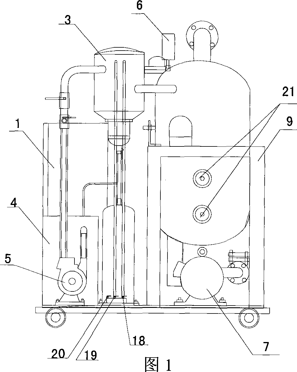
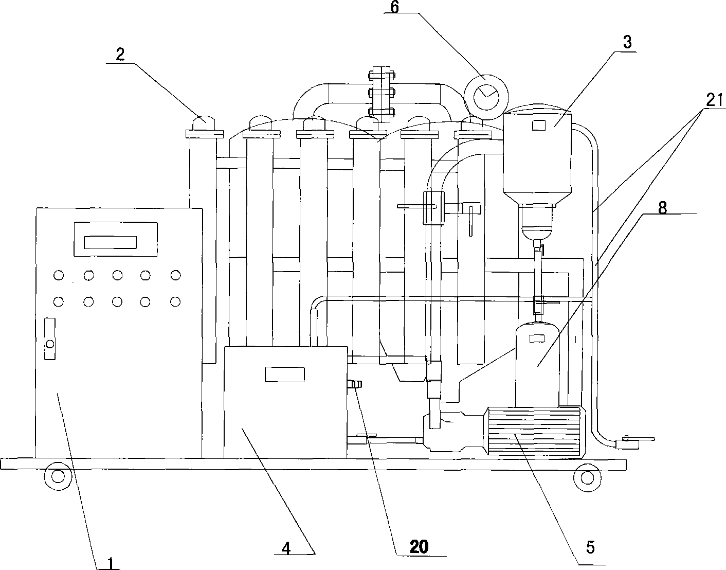
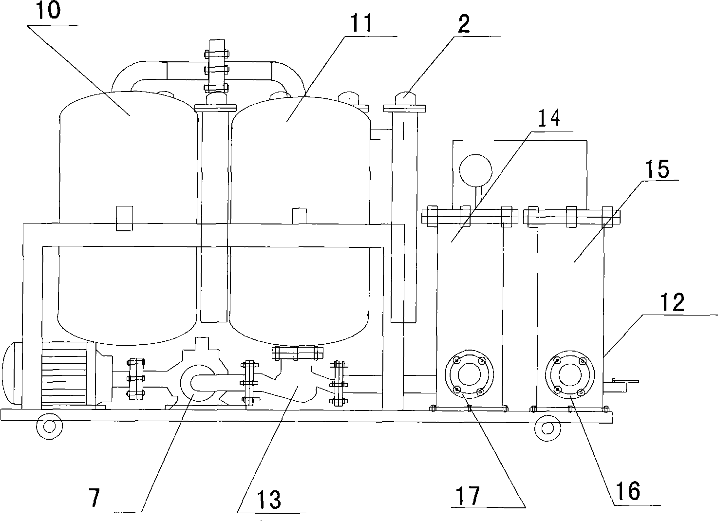
The invention relates to an intellectualization high-efficient automatic oil purifying device, which is favorable to desorbing the water, air, impurities and the like in oil with high efficiency at high speed so as to cause turbid oil to become clear and the structure to be more scientific and compacter, decrease the device volume and save raw materials and achieve the purpose of dehydration with high efficiency. In the device, the inlet of a strainer (15) is an oil inlet (16), the outlet of the strainer (15) is connected with the inlet of a heater (2) through an oil-feed pump (12), the outlet of the heater (2) is connected with a separation chamber (10), the upper parts of the separation chamber (10) and an atomizing chamber (11) are communicated, the lower part of the atomizing chamber (11) is communicated with the inlet of a secondary filter (14) through a reflux valve (13) and an oil scavenging pump (7), and the outlet of the secondary filter (14) is an oil outlet (17); and one end of a vacuum pump (5) is connected with a cyclic water tank (4), the other end thereof is connected with the upper part of a condenser (3), the other side of the upper part of the condenser (3) is communicated with the upper part of the atomizing chamber (11) and the lower part of the condenser (3) is connected with an automatic drainage device (8).

Description

technical field [0001] The invention is an oil purification device for high-viscosity oil of large-scale mechanical equipment, which can filter impurities in high-viscosity oil when the mechanical equipment is running, remove moisture and air, and achieve various purification indicators of pure high-viscosity oil , belongs to the manufacturing field of oil purifiers. Background technique [0002] Mechanical equipment relies on the lubrication and adjustment of high-viscosity oil to maintain its normal operation, and high-viscosity oil has a good lubricating effect on the operation and maintenance of mechanical equipment, especially in industries that use large-scale mechanical equipment, the use of high-viscosity oil The amount is large. When hydraulic oil, mechanical oil, cooling oil and other lubricating oils are used in the process of mechanical operation, moisture, gas, volatile substances and impurities will inevitably be mixed into the lubricating oil due to various r...

Claims


Application Information

Patent Timeline
IPC IPC(8): C10M175/00
Inventor 丁恒井
Owner 镇江市长江机电设备厂有限公司
Learn More