Directional control valve driven by hydraulic pressure

A technology for directional control valves and water pressure, applied in fluid pressure actuators, valve details, valve devices, etc., can solve problems such as high vaporization pressure, material corrosion, wire drawing erosion, etc., and achieve component cost reduction, long service life, Good sealing effect

Inactive Publication Date: 2009-04-01
HANGZHOU WATER TREATMENT TECH DEV CENT
View PDF0 Cites 5 Cited by
  • Summary
  • Abstract
  • Description
  • Claims
  • Application Information

AI Technical Summary

Problems solved by technology

However, the research on hydraulic valves is not a simple process of changing the working medium of hydraulic valves into water.
Due to the differences in physical and chemical properties between water and mineral oil, such as low viscosity, high vaporization pressure, and strong corrosion, hydraulic valves face problems such as serious cavitation and wire drawing erosion, material corrosion, and large leakage.
my country's hydraulic reversing valve basically still uses the hydraulic reversing valve structure, which is complex in structure, easy to wear and leak, and affects the working efficiency of the system

Method used


Image

  • Directional control valve driven by hydraulic pressure
  • Directional control valve driven by hydraulic pressure
  • Directional control valve driven by hydraulic pressure

Examples


Embodiment Construction

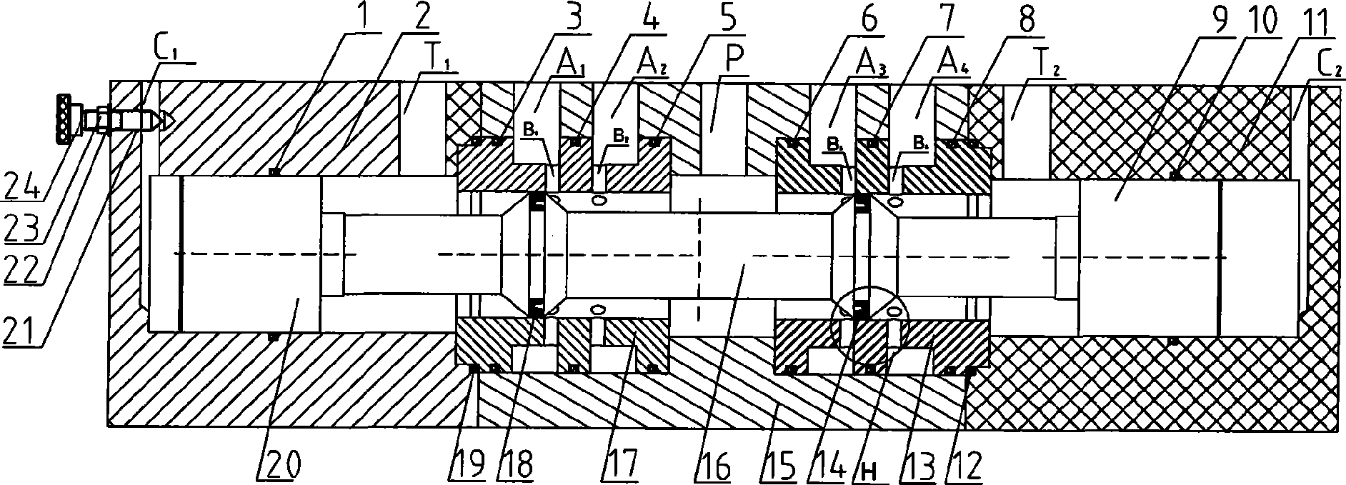
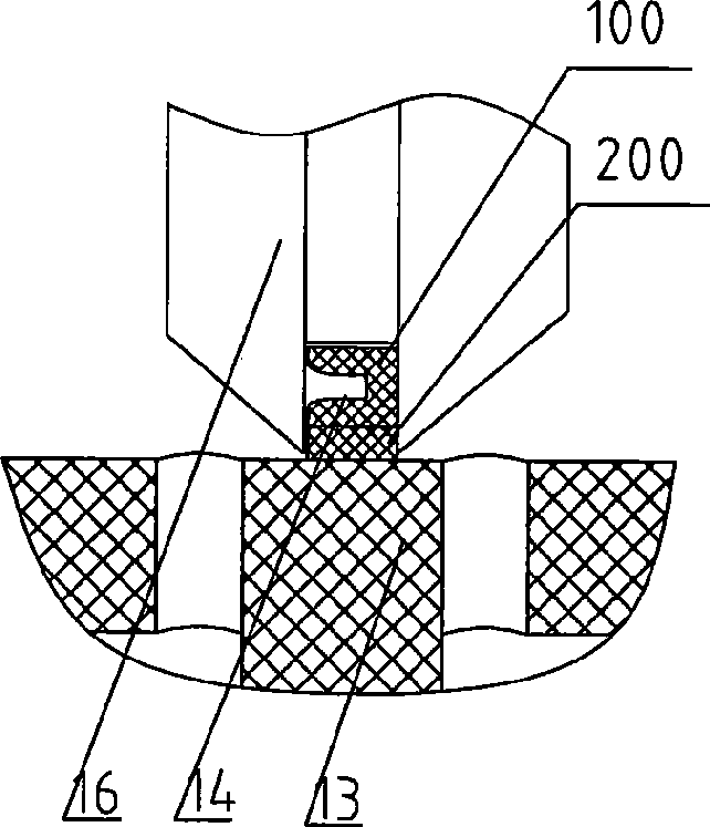
[0024] Refer to attached picture. The present invention is provided with a valve seat 15, and the valve seat is respectively provided with a first water port A from left to right. 1 , the second water port A 2 , Pressure water inlet P, third water outlet A 3 , the fourth water outlet A 4 ;

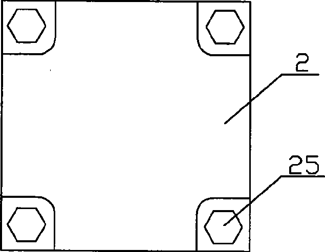
[0025] The directional control valve is also provided with a left valve cover 2 connected to the left side of the valve seat and a right valve cover 11 connected to the right side of the valve seat, and the left valve cover 2 is provided with a first pilot water port C from left to right 1 , the first outlet T 1 , the right valve cover 11 is provided with a second pilot water hole C from right to left 2 , the second outlet T 2 ; The left bonnet 2 and the right bonnet 11 are fixed to the left and right sides of the valve seat 15 with bolts 25, respectively, so that the installation is simpler.

[0026] Described directional control valve installs the first porous ring 17 in the left ...


PUM


Abstract

The invention provides a hydraulic driving directional control valve which is provided with a valve base. The valve base is provided with a first water intake, a second water intake, a pressure water inlet, a third water intake and a forth water intake respectively from left to right. The directional control valve adopts the hydraulic drive of pressure water which is guided into a hydraulic driving chamber by a pilot control opening to drive a piston to act, cause a valve stem to move, and further control the on-off and the flowing direction of water flow so as to control the action of an actuator, thereby saving energy and protecting the environment; in addition, the valve stem is light in weight, short in stroke, and smooth, quick and liable in switching. Simultaneously, the technical proposal adopted by the directional control valve has good sealing effect and long service life, and needs no valve core or valve sleeve of expensive ceramic materials, thereby greatly reducing the cost on elements. The directional control valve is particularly applicable to sea water, fresh water and a hydraulic medium with high water base and low viscosity.

Description

technical field [0001] The invention relates to a hydraulically driven directional control valve, which is suitable for hydraulic systems. Background technique [0002] The water hydraulic transmission technology that directly uses natural seawater or fresh water as the hydraulic working medium has the characteristics of safety, compatibility with the environment, compatibility with products, system simplification, energy saving, economy, sanitation, etc., and can satisfy people's needs for safety, economy and The desire for environmental protection and other aspects meets the needs of sustainable development of human beings, and has become a frontier topic in the field of international hydraulic technology today, with extremely broad application prospects. [0003] The hydraulic directional control valve plays an important role in controlling the flow of fluid and the direction of flow in the hydraulic system to control the movement of the actuator. Since the early 1990s i...

Claims


Application Information

Patent Timeline
Patent Type & Authority Applications(China)
IPC IPC(8): F15B13/02F16K31/122
Inventor 张希建张建中谭斌谭永文樊雄
Owner HANGZHOU WATER TREATMENT TECH DEV CENT
Why Eureka
Try Eureka